

Consider Figure E17.6(a), in which the overall heat transfer coefficient (U) is assumed to be 25 W/m
Question:
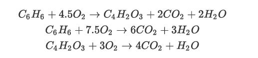
Consider Figure E17.6(a), in which the overall heat transfer coefficient (U) is assumed to be 25 W/m °C. It can be noted that in Figures E17.6(b) and E17.6(c)(b), the transients in exit temperature and CO concentration appear to be negligible. Now increase the flowrate of benzene to 0.01 kmol/h, while keeping the flowrate of air constant. Simultaneously increase the temperature of air to 520°C. Did you notice any difference in the transient profile of temperature and benzene and CO concentration at the exit of the reactor compared to what is obtained in Example 17.6? Why or why not?
Example 17.6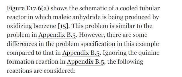
![]()
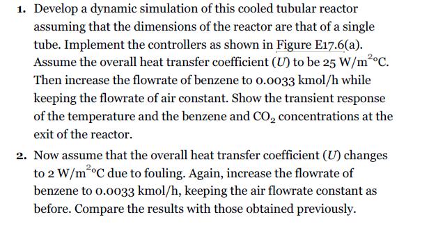
Figure E17.6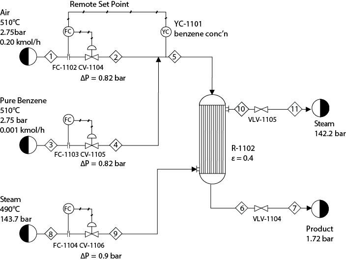
Fantastic news! We've Found the answer you've been seeking!
Step by Step Answer:

Answered By
Sufiyan Ahmed Tariq
I am a Chartered Accountant and an Associate Public & Finance Accountant. I also hold a bachelors of Commerce degree. I have over 8 years of experience in accounting, finance and auditing. Through out my career, I have worked with many leading multinational organisation.
I have helped a number of students in studies by teaching them key concepts of subjects like accounting, finance, corporate law and auditing. I help students understanding the complex situation by providing them daily life examples.
I can help you in the following subject / areas:
a) Accounting;
b) Finance;
c) Commerce;
d) Auditing; and
e) Corporate Law.
7+ Reviews
17+ Question Solved
Related Book For 
Analysis Synthesis And Design Of Chemical Processes
ISBN: 9780134177403
5th Edition
Authors: Richard Turton, Joseph Shaeiwitz, Debangsu Bhattacharyya, Wallace Whiting
Question Posted:
