

In a particular electric circuit, called a low-pass filter, the input voltage V i is across a
Question:
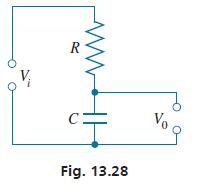
In a particular electric circuit, called a low-pass filter, the input voltage Vi is across a resistor and a capacitor, and the output voltage V0 is across the capacitor (see Fig. 13.28). The voltage gain G (in dB) is given by
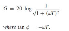
Here, ∅ is the phase angle of V0/Vi. For values of ωT of 0.01, 0.1, 0.3, 1.0, 3.0, 10.0, 30.0, and 100, plot the indicated graphs. These graphs are called a Bode diagram for the circuit.
Calculate values of G for the given values of ωT and plot a semilogarithmic graph of G vs. ωT.
Fantastic news! We've Found the answer you've been seeking!
Step by Step Answer:
To calculate the voltage gain G for the given values of T we can use the ...View the full answer

Answered By
Mary Boke
I have teached the student upto class 12th as well as my fellow mates.I have a good command in engineering,maths and science.I scored 90+ marks in 10th and 12th in maths.
0 Reviews
10+ Question Solved
Related Book For 

Basic Technical Mathematics
ISBN: 9780137529896
12th Edition
Authors: Allyn J. Washington, Richard Evans
Question Posted:
