

The mechanical governor shown in Figure P9.66 was invented by James Watt (Chapter 6) to regulate and
Question:
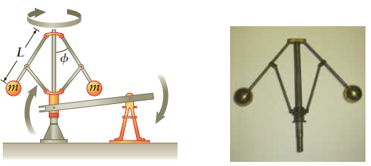
The mechanical governor shown in Figure P9.66 was invented by James Watt (Chapter 6) to regulate and limit, through feedback, a steam engine?s maximum speed. The device consists of two spherical masses connected via lightweight metal arms that can simultaneously rotate about a shaft and pivot outward from a hinge at the top, allowing, depending on the rotation rate, the masses to rise. Two more rods connect the arms to a collar that can slide up and down the shaft, controlling a lever that can be connected to a switch or valve that regulates the flow of fuel to the engine. In this case, the governor is designed to cut off power when the shaft rotates at 150 rpm (or higher).?
(a) If the lever activates a switch when the mass arm makes an angle ? = 75? with respect to the shaft, what length L should the connecting rod have to make the governor work as planned? Assume the connecting rods are made of very lightweight material.?
(b) If each mass is 250 g, approximately how much rotational kinetic energy does the governor have at the time of cutoff??
(c) What is the angular momentum of the governor at this time? How would using spheres of larger mass affect the governor?s response time to changes in rotational speed?
Figure P9.66
?
Step by Step Answer:
The masses move in a horizontal circle and are therefore subject to a horizontal centripetal acceleration provided by the rod In the vertical directio...View the full answer


College Physics Reasoning and Relationships
ISBN: 978-0840058195
2nd edition
Authors: Nicholas Giordano
