

Modify Program 5.1 by adding the noperspective declaration to the texture coordinate vertex attributes, as described in
Question:
Modify Program 5.1 by adding the “noperspective” declaration to the texture coordinate vertex attributes, as described in Section 5.11. Then rerun the program and compare the output with the original. Is any perspective distortion evident?
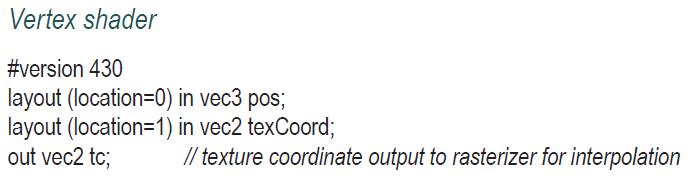
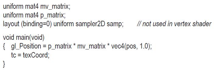
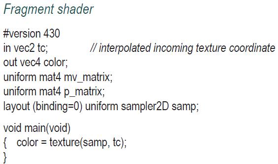
Program 5.1
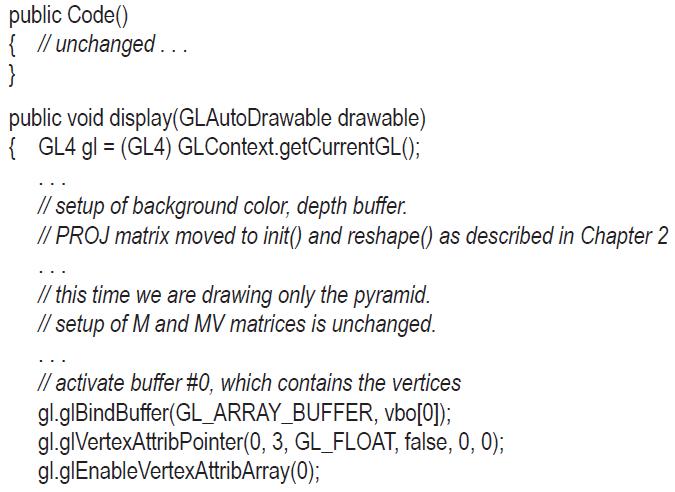
![} // activate buffer #1, which contains the texture coordinates gl.glBindBuffer(GL_ARRAY_BUFFER, vbo[1]);](https://dsd5zvtm8ll6.cloudfront.net/images/question_images/1701/6/7/1/865656d73b90aba41701671864435.jpg)
![private void setupVertices() { GL4 gl = (GL4) GLContext.getCurrentGL(); float[] pyramidPositions = { /* data](https://dsd5zvtm8ll6.cloudfront.net/images/question_images/1701/6/7/1/888656d73d083a401701671887892.jpg)
Section 5.11
We have seen that as texture coordinates are passed from the vertex shader to the fragment shader, they are interpolated as they pass through the rasterizer. We have also seen that this is the result of the automatic linear interpolation that is always performed on vertex attributes.
However, in the case of texture coordinates, linear interpolation can lead to noticeable distortion in a 3D scene with perspective projection. Consider a rectangle made of two triangles and textured with a checkerboard image, facing the camera. As the rectangle is rotated around the X axis, the top part of the rectangle tilts away from the camera, while the lower part of the rectangle swings closer to the camera. Thus, we would expect the squares at the top to become smaller and the squares at the bottom to become larger. However, linear interpolation of the texture coordinates will instead cause the height of all squares to be equal. The distortion is exacerbated along the diagonal defining the two triangles that make up the rectangle. The resulting distortion is shown in Figure 5.16.
Fortunately, there are algorithms for correcting perspective distortion, and by default, OpenGL applies a perspective correction algorithm [OP14, SP16] during rasterization. Figure 5.17 shows the same rotating checkerboard, properly rendered by OpenGL.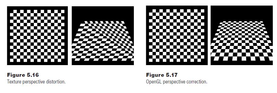
Although not common, it is possible to disable OpenGL’s perspective correction by adding the keyword “noperspective” in the declaration of the vertex attribute containing the texture coordinates. This has to be done in both the vertex and fragment shaders. For example, the vertex attribute in the vertex shader of Program 5.1 would be declared as follows:![]()
The corresponding attribute in the fragment shader would be declared![]()
This second syntax was in fact used to produce the distorted checkerboard in Figure 5.16.
Step by Step Answer:


Computer Graphics Programming In OpenGL With JAVA
ISBN: 9781683922193
2nd Edition
Authors: V. Scott Gordon PhD, John L. Clevenger PhD
