

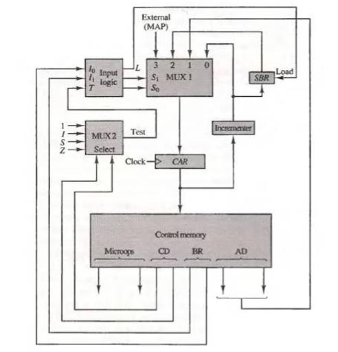
Insert an exclusive-OR gate between MUX 2 and the input logic of Fig. 7-8. One input to
Question:
Insert an exclusive-OR gate between MUX 2 and the input logic of Fig. 7-8. One input to the gate comes from the test output of the multiplexer. The other input to the gate comes from a bit labeled P (for polarity) in the microinstruction from control memory. The output of the gate goes to the input T of the input logic. What does the polarity control P accomplish?
Fig. 7-8
Fantastic news! We've Found the answer you've been seeking!
Step by Step Answer:
The introduction of an exclusiveOR XOR gate between MUX 2 and the input logic of the given system wi...View the full answer

Answered By
Susan Juma
I'm available and reachable 24/7. I have high experience in helping students with their assignments, proposals, and dissertations. Most importantly, I'm a professional accountant and I can handle all kinds of accounting and finance problems.
15+ Reviews
45+ Question Solved
Related Book For 
Question Posted:
