

The following control inputs are active in the bus system shown in Fig. 5-4. For each case,
Question:
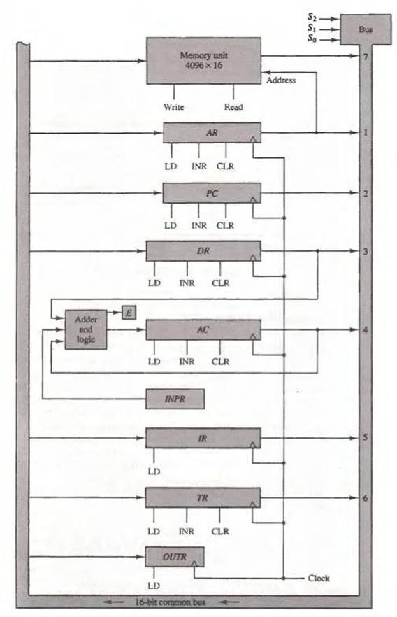
The following control inputs are active in the bus system shown in Fig. 5-4. For each case, specify the register transfer that will be executed during the next clock transition.
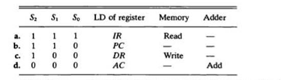
Fig. 5-4
Fantastic news! We've Found the answer you've been seeking!
Step by Step Answer:
Lets examine the provided control inputs and ascertain the action that will be carried out during th...View the full answer

Answered By
Ashad Ahmad
I have some tutoring experience my self. I tutored many students in the past. I have even tutored my own brother, in conclusion I am experienced in tutoring department.
In my education, I have incontered many tutors and those tutor inspired me to became a tutor.
0 Reviews
10+ Question Solved
Related Book For 
Question Posted:
