

Consider a slightly different block-diagram for the closed-loop single-machine infinite-bus power system of Fig. 1-13 as shown
Question:
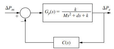
Consider a slightly different block-diagram for the closed-loop single-machine infinite-bus power system of Fig. 1-13 as shown below in Fig. P1.7-3. In this block diagram the controller \(C(s)\) is placed in cascade to the plant instead of in the feedback loop. The feedback gain is considered as unity.
(a) For this set-up compute the steady-state error between a unit step input \(\Delta P_{m}\) and the output \(\Delta P_{e}\) for the following controller transfer functions:
(i) \(C(s)=a_{0}\) (proportional, or \(P\)-controller)
(ii) \(C(s)=a_{0}+a_{1} s\) (proportional + derivative, or PD controller)
(iii) \(C(s)=a_{0}+\frac{a_{2}}{s}\) (proportional + integral, or PI controller)
(iv) \(C(s)=a_{0}+a_{1} s+\frac{a_{2}}{s}\) (proportional + integral + derivative, or PID controller)
(b) Using \(M=0.5, d=0.1\), and \(k=10\), and a PID controller \(C(s)=1+2 s+\frac{10}{s}\), compute the rise time of \(\Delta P_{e}\). How does the rise time change when the derivative gain is doubled?
Fig. P1.7-3
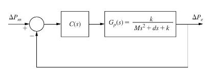
Fig. 1-13
Step by Step Answer:


Digital Control System Analysis And Design
ISBN: 9781292061221
4th Global Edition
Authors: Charles Phillips, H. Nagle, Aranya Chakrabortty
