

Given the plant of Problem 11.4-9, with the cost function (a) Calculate the feedback gains required to
Question:
Given the plant of Problem 11.4-9, with the cost function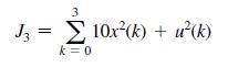
(a) Calculate the feedback gains required to minimize the cost function, using the difference-equation approach of Section 11.4.
(b) Find the maximum magnitude of u(k) as a function of x(0).
(c) Compare the maximum magnitude of u(k) in part
(b) with the value in Problem 11.4-9(c). Explain the difference.
Problem 11.4-9
A chamber temperature control system is modeled as shown in Fig. P11.4-8. This system is described in Problem 1.6-1. For this problem, ignore the disturbance input, T = 0.6 s and let D(z) = 1. It was shown in Problem 9.2-3 that the plant state model is given by![x(k+ 1) = 0.7408x(k)+1.0368u(k) Let the cost function be given by 3 J3 = [2x(k) + u(k)] k = 0](https://dsd5zvtm8ll6.cloudfront.net/images/question_images/1705/6/4/6/06765aa17f35e2761705646066199.jpg)
(a) Calculate the feedback gains required to minimize the cost function, using the partial-differentiation procedure of Section 11.3.
(b) Repeat part (a), using the difference-equation approach of Section 11.4.
(c) Find the maximum magnitude of u(k) as a function of x(0).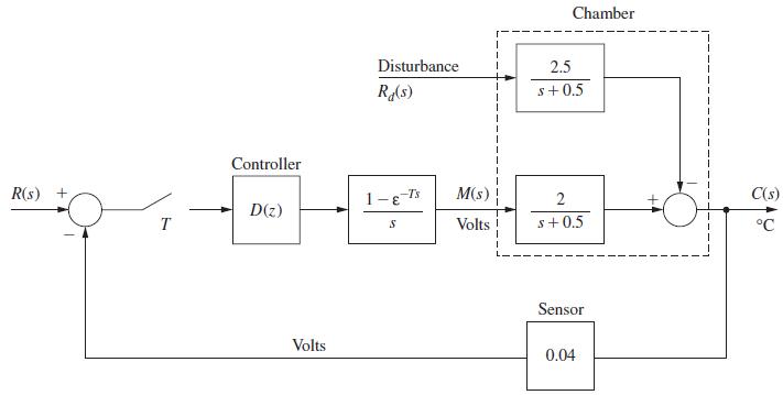
Problem 1.6-1
It is shown in [6] that given the partitioned matrix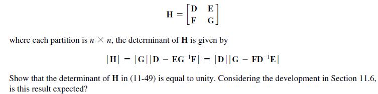
Problem 9.2-3
A chamber temperature control system is modeled as shown in Fig. P9.2-3. This system is described in
Problem 1.6-1. For this problem, ignore the disturbance input, T = 0.6 s, and let D(z) = 1. It was shown
in Problem 6.2-4 that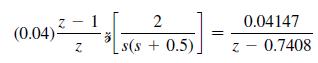
Note that the sensor gain is included in this transfer function.
(a) Draw a flow graph of the plant and sensor. Write the state equations with the state variable x(k) equal to
the system output and the output y(k) equal to the sensor output.
(b) Find the time constant v for this closed-loop system.
(c) Using pole-placement design, find the gain K that yield the closed-loop time constant τ = 1 s . Note
that the sensor gain does not enter these calculations.
(d) Show that the gain K in part (b) yields the desired closed-loop characteristic equation, using (9-15).
(e) Draw a block diagram for the system that includes the sensor. Let the digital computer realize a gain,
K1, such that the closed-loop time constant is as given in part (b). The sensor in this system must have
the gain given.
(f) Using the characteristic equation for the block diagram of part (e),![]()
verify that this block diagram yields the desired characteristic equation.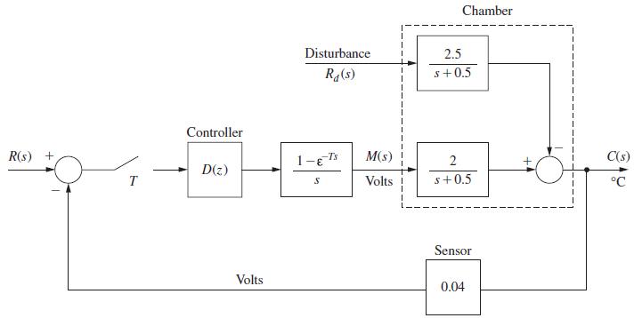
Step by Step Answer:

This question has not been answered yet.
You can Ask your question!

Digital Control System Analysis And Design
ISBN: 9780132938310
4th Edition
Authors: Charles Phillips, H. Nagle, Aranya Chakrabortty
