

The block diagram of a control system of a joint in a robot arm is shown in
Question:
The block diagram of a control system of a joint in a robot arm is shown in Fig. P6.2-7. Let T = 0.1 s , K = 10 , and D(z) = 1 . The results of Problem 6.2-7 are useful in this problem if these results are available.
(a) Find the damping ratio ζ , the natural frequency ωn , and the time constant τ of the open-loop system. If the system characteristic equation has two real zeros, find the two time constants.
These values can be solved by inspection. Why?
(b) Repeat part (a) for the closed-loop system.
(c) Repeat parts (a) and (b) for the system with the sampler, digital controller, and data hold removed, that is, for the analog system.
(d) Use the results in parts (b) and (c) to find the percent overshoot in the step responses for the sampled-data closed-loop system and for the analog closed-loop system.
Problem 6.2-7
The block diagram of a control system of a joint in a robot arm is shown in Fig. P6.2-7. This system is discussed in Section 1.6. Let T = 0.1 s and D(z) = 1.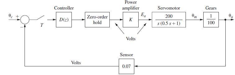
Step by Step Answer:
a The openloop system has the characteristic of Gs poles at s 0 40 s2 T 05s b From Problem 627 ...View the full answer


Digital Control System Analysis And Design
ISBN: 9780132938310
4th Edition
Authors: Charles Phillips, H. Nagle, Aranya Chakrabortty
