

In the system of Figure 10-33, A, B, and C are BILBO registers. The B 1 and
Question:
B1B2= 00, shift register; B1B2= 01, PRPG (pattern generator); B1B2= 10, normal system mode; B1B2= 11, MISR (signature register). The shifting into A, B, and C is always LSB first. When in the test mode, the Dbus is not used. Specify the sequence of the tester outputs (B1, B2, and Si) needed to perform the following operations:
1. Load A with 1011 and B with 1110; clear C.
2. Test the system by using A and B as pattern generators and C as a signature register for four clock times.
3. Shift the C register output into the tester.
4. Return to the normal system mode.
B1 B2 Si = 0 0 0,
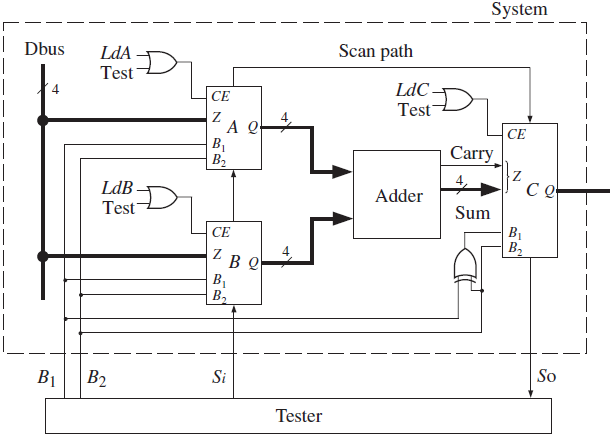
Figure 10-33: System with BILBO Registers and Tester
Fantastic news! We've Found the answer you've been seeking!
Step by Step Answer:
1 Load A with 1011 and B with 1110 clear C 2 Test the system by using A and B as patter...View the full answer

Answered By
PALASH JHANWAR
I am a Chartered Accountant with AIR 45 in CA - IPCC. I am a Merit Holder ( B.Com ). The following is my educational details.
PLEASE ACCESS MY RESUME FROM THE FOLLOWING LINK: https://drive.google.com/file/d/1hYR1uch-ff6MRC_cDB07K6VqY9kQ3SFL/view?usp=sharing
3+ Reviews
10+ Question Solved
Related Book For 
Digital Systems Design Using Verilog
ISBN: 978-1285051079
1st edition
Authors: Charles Roth, Lizy K. John, Byeong Kil Lee
Question Posted:
