

Add another flip-flop, E, to the counter of Figure 7-1. The clock signal is an 8-MHz square
Question:
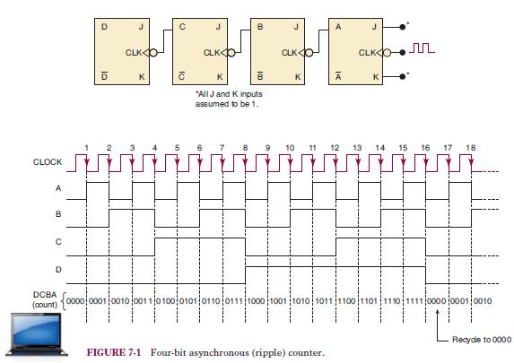
Add another flip-flop, E, to the counter of Figure 7-1. The clock signal is an 8-MHz square wave.
(a) What will be the frequency at the E output? What will be the duty cycle of this signal?
(b) Repeat (a) if the clock signal has a 20% duty cycle.
(c) What will be the frequency at the C output?
(d) What is the MOD number of this counter?
Figure 7-1
Fantastic news! We've Found the answer you've been seeking!
Step by Step Answer:

Answered By
Mehwish Aziz
What I have learnt in my 8 years experience of tutoring is that you really need to have a friendly relationship with your students so they can come to you with their queries without any hesitation. I am quite hardworking and I have strong work ethics. Since I had never been one of those who always top in the class and always get A* no matter what, I can understand the fear of failure and can relate with my students at so many levels. I had always been one of those who had to work really hard to get decent grades. I am forever grateful to some of the amazing teachers that I have had who made learning one, and owing to whom I was able to get some extraordinary grades and get into one of the most prestigious universities of the country. Inspired by those same teachers, I am to be like one of them - who never gives up on her students and always believe in them!
3+ Reviews
10+ Question Solved
Related Book For 

Digital Systems Principles And Application
ISBN: 9780134220130
12th Edition
Authors: Ronald Tocci, Neal Widmer, Gregory Moss
Question Posted:
