

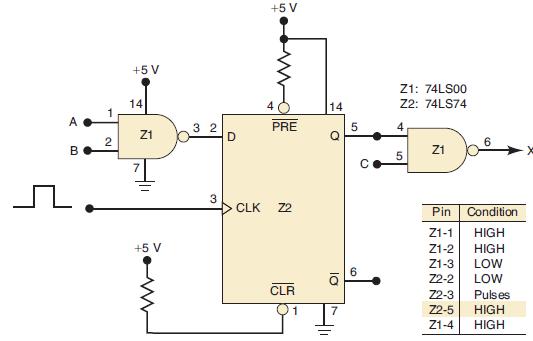
Consider the circuit in Figure 5-66 and examine the logic probe indications shown in the accompanying table.
Question:
Consider the circuit in Figure 5-66 and examine the logic probe indications shown in the accompanying table. There is a LOW at the D input of the FF when pulses are applied to its CLK input, but the Q output fails to go to the LOW state. The technician testing this circuit considers each of the following possible circuit faults:
1. Z2-5 is internally shorted to VCC.
2. Z1-4 is internally shorted to VCC.
3. Z2-5 or Z1-4 is externally shorted to VCC.
4. Z2-4 is internally or externally shorted to GROUND. This would keep P̅R̅E̅ activated and would override the CLK input.
5. There is an internal failure in Z2 that prevents FF Q from responding properly to its inputs.
The technician, after making the necessary ohmmeter checks, rules out the first four possibilities. He also checks Z2’s VCC and GROUND pins and finds that they are at the proper voltages. He is reluctant to unsolder Z2 from the circuit until he is certain that it is faulty, and so he decides to look at the clock signal. He uses an oscilloscope to check its amplitude, frequency, pulse width, and transition times. He finds that they are all within the specifications for the 74LS74. Finally, he concludes that Z2 is faulty.
He removes the 74LS74 chip and replaces it with another one. To his dismay, the circuit with the new chip behaves in exactly the same way. After scratching his head, he decides to change the NAND gate chip, although he doesn’t know why. As expected, he sees no change in the circuit operation.
Becoming more puzzled, he recalls that his electronics lab instructor emphasized the value of performing a thorough visual check on the circuit board, and so he begins to examine it carefully. While he is doing that, he detects a solder bridge between pins 6 and 7 of Z2. He removes it and tests the circuit, and it functions correctly. Explain how this fault produced the operation observed.
Figure 5-66
Step by Step Answer:
The solder bridge was shorting the Q output to GROUND This means that Q i...View the full answer


Digital Systems Principles And Application
ISBN: 9780134220130
12th Edition
Authors: Ronald Tocci, Neal Widmer, Gregory Moss
