

Figure 12-46(a) shows a circuit that generates the RAS, CAS, and MUX signals needed for proper operation
Question:
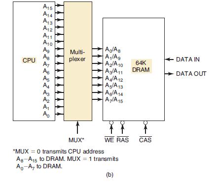
Figure 12-46(a) shows a circuit that generates the R̅A̅S̅, C̅A̅S̅, and MUX signals needed for proper operation of the circuit of Figure 12-27(b). The 10-MHz master clock signal provides the basic timing for the computer. The memory request signal (MEMR) is generated by the CPU in synchronism with the master clock, as shown in part (b) of the figure. MEMR is normally LOW and is driven HIGH whenever the CPU wants to access memory for a read or a write operation. Determine the waveforms at Q0, Q̅1, and Q2, and compare them with the desired waveforms of Figure 12-28.
Figure 12-46
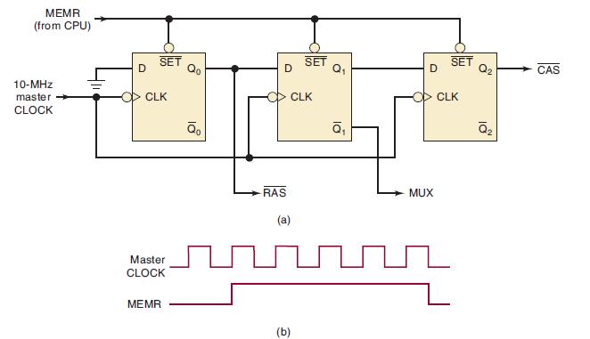
Figure 12-27(b)
Fantastic news! We've Found the answer you've been seeking!
Step by Step Answer:

Answered By
AJIN KURIAKOSE
I HAVE ELECTRONICS ENGINEERING DEGREE..AND MY AREA OF INTEREST IS MATHEMATICS,CONTROL SYSTEM,NETWORK,DIGITAL
21+ Reviews
32+ Question Solved
Related Book For 

Digital Systems Principles And Application
ISBN: 9780134220130
12th Edition
Authors: Ronald Tocci, Neal Widmer, Gregory Moss
Question Posted:
