

Figure 3-60 shows an application of logic gates that simulates a two way switch like the ones
Question:
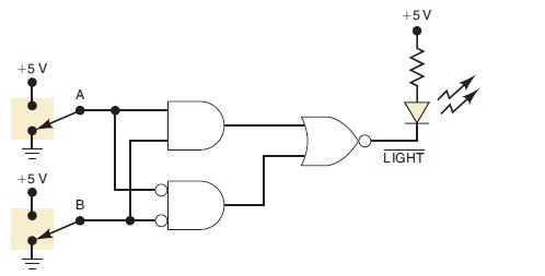
Figure 3-60 shows an application of logic gates that simulates a two way switch like the ones used in our homes to turn a light on or off from two different switches. Here the light is an LED that will be ON (conducting) when the NOR gate output is LOW. Note that this output is labeled
![]()
to indicate that it is active-LOW. Determine the input conditions needed to turn on the LED. Then verify that the circuit operates as a two-way switch using switches A and B. (In Chapter 4, you will learn how to design circuits like this one to produce a given relationship between inputs and outputs.)
Figure 3-60
Fantastic news! We've Found the answer you've been seeking!
Step by Step Answer:

Answered By
Pranav Makode
I am a bachelor students studying at professor ram meghe institute of technology and research. I have a great experience of being an expert. I have worked as an expert at helloexperts and solvelancer as a part time job. I have also worked as a doubt solver at ICAD SCHOOL OF LEARNING, which is in Amravati city. I have also worked as an Freelancer.
I have great experience of helping students, as described above. I can help any students in a most simple and understandable way. I will not give you have any chance for complaint. You will be greatfull to accept me as an expert.
1+ Reviews
10+ Question Solved
Related Book For 

Digital Systems Principles And Application
ISBN: 9780134220130
12th Edition
Authors: Ronald Tocci, Neal Widmer, Gregory Moss
Question Posted:
