

Figure 4-69 shows a diagram for an automobile alarm circuit used to detect certain undesirable conditions. The
Question:
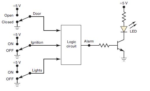
Figure 4-69 shows a diagram for an automobile alarm circuit used to detect certain undesirable conditions. The three switches are used to indicate the status of the door by the driver’s seat, the ignition, and the headlights, respectively. Design the logic circuit with these three switches as inputs so that the alarm will be activated whenever either of the following conditions exists:
■ The headlights are on while the ignition is off.
■ The door is open while the ignition is on.
Figure 4-69
Fantastic news! We've Found the answer you've been seeking!
Step by Step Answer:

Answered By
Rohit Kumar Bansal
I don't have any experience in online teaching, but yes I'm teaching at online platform for last 7 years.
I qualified my CA exams in may 2018.
0 Reviews
10+ Question Solved
Related Book For 

Digital Systems Principles And Application
ISBN: 9780134220130
12th Edition
Authors: Ronald Tocci, Neal Widmer, Gregory Moss
Question Posted:
