

Figure 4-72 shows four switches that are part of the control circuitry in a copy machine. The
Question:
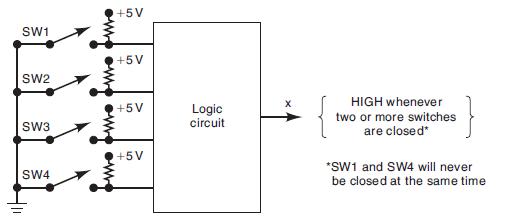
Figure 4-72 shows four switches that are part of the control circuitry in a copy machine. The switches are at various points along the path of the copy paper as the paper passes through the machine. Each switch is normally open, and as the paper passes over a switch, the switch closes. It is impossible for switches SW1 and SW4 to be closed at the same time. Design the logic circuit to produce a HIGH output whenever two or more switches are closed at the same time. Use K mapping and take advantage of the don’t-care conditions.
Figure 4-72
Fantastic news! We've Found the answer you've been seeking!
Step by Step Answer:

Answered By
David Muchemi
I am a professional academic writer with considerable experience in writing business and economic related papers. I have been writing for my clients who reach out to me personally after being recommended to me by satisfied clients.
I have the English language prowess, no grammatical and spelling errors can be found in my work. I double-check for such mistakes before submitting my papers.
I deliver finished work within the stipulated time and without fail. I am a good researcher on any topic especially those perceived to be tough.
I am ready to work on your papers and ensure you receive the highest quality you are looking for. Please hire me to offer my readily available quality service.
Best regards,
27+ Reviews
61+ Question Solved
Related Book For 

Digital Systems Principles And Application
ISBN: 9780134220130
12th Edition
Authors: Ronald Tocci, Neal Widmer, Gregory Moss
Question Posted:
