

Figure 9-76 shows the block diagram of a logic circuit used to control the number of copies
Question:
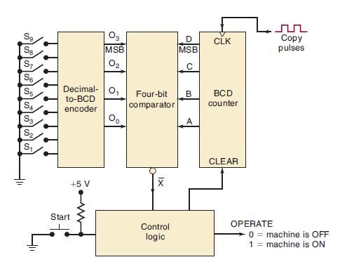
Figure 9-76 shows the block diagram of a logic circuit used to control the number of copies made by a copy machine. The machine operator selects the number of desired copies by closing one of the selector switches S1 to S9. This number is encoded in BCD by the encoder and is sent to a comparator circuit. The operator then hits a momentary contact START switch, which clears the counter and initiates a HIGH OPERATE output that is sent to the machine to signal it to make copies. As the machine makes each copy, a copy pulse is generated and fed to the BCD counter. The counter outputs are continually compared with the switch encoder outputs by the comparator. When the two BCD numbers match, indicating that the desired number of copies has been made, the comparator output X̅ goes LOW; this causes the OPERATE level to return LOW and stop the machine so that no more copies are made. Activating the START switch will cause this process to be repeated. Design the complete logic circuitry for the comparator and control sections of this system.
Figure 9-76
Step by Step Answer:


Digital Systems Principles And Application
ISBN: 9780134220130
12th Edition
Authors: Ronald Tocci, Neal Widmer, Gregory Moss
