

Figure 9-79 shows how a multiplexer can be used to generate logic waveforms with any desirable pattern.
Question:
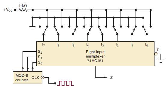
Figure 9-79 shows how a multiplexer can be used to generate logic waveforms with any desirable pattern. The pattern is programmed using eight SPDT switches, and the waveform is repetitively produced by pulsing the MOD-8 counter. Draw the waveform at Z for the given switch positions.
Figure 9-79
Fantastic news! We've Found the answer you've been seeking!
Step by Step Answer:
With the given switch positions the multiplexer will select the ...View the full answer

Answered By
Hillary Waliaulah
As a tutor, I am that experienced with over 5 years. With this, I am capable of handling a variety of subjects.
17+ Reviews
30+ Question Solved
Related Book For 

Digital Systems Principles And Application
ISBN: 9780134220130
12th Edition
Authors: Ronald Tocci, Neal Widmer, Gregory Moss
Question Posted:
