

Now that the circuitry of Figure 9-85 has been added to Figure 9-47, a total of five
Question:
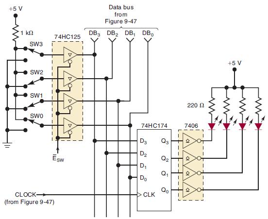
Now that the circuitry of Figure 9-85 has been added to Figure 9-47, a total of five devices are connected to the data bus. The circuit in Figure 9-85(a) will now be used to generate the enable signals needed to perform the different data transfers over the data bus. It uses a 74HC139 chip that contains two identical independent 1-of-4 decoders with an active-LOW enable. The top decoder is used to select the device that will put data on the data bus (output select), and the bottom decoder is used to select the device that is to take the data from the data bus (input select). Assume that the decoder outputs are connected to the corresponding enable inputs of the devices tied to the data bus. Also assume that all registers initially contain 0000 at time t0, and the switches are in the positions shown in Figure 9-84.
(a) Determine the contents of each register at times t1, t2, and t3 in response to the waveforms in Figure 9-85(b).
(b) Can bus contention ever occur with this circuit? Explain.
Figure 9-85
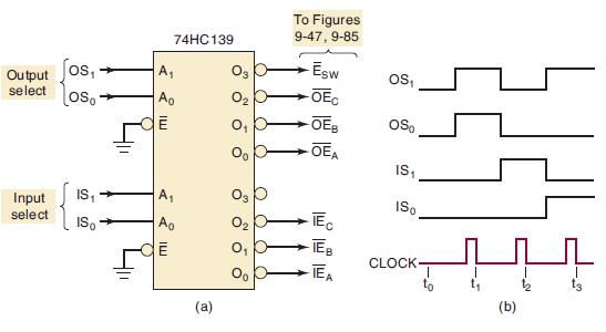
Figure 9-47
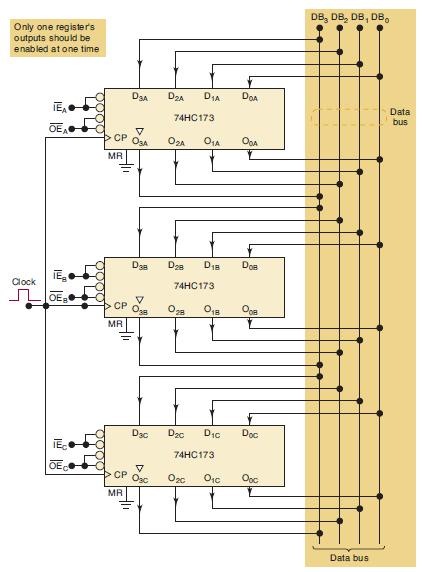
Figure 9-84
Step by Step Answer:


Digital Systems Principles And Application
ISBN: 9780134220130
12th Edition
Authors: Ronald Tocci, Neal Widmer, Gregory Moss
