

The circuit of Figure 9-80 shows how an eight-input MUX can be used to generate a four-variable
Question:
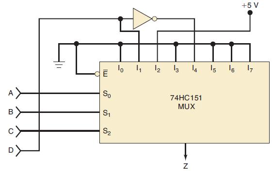
The circuit of Figure 9-80 shows how an eight-input MUX can be used to generate a four-variable logic function, even though the MUX has only three SELECT inputs. Three of the logic variables A, B, and C are connected to the SELECT inputs. The fourth variable D and its inverse D are connected to selected data inputs of the MUX as required by the desired logic function. The other MUX data inputs are tied to a LOW or a HIGH as required by the function.
(a) Set up a truth table showing the output Z for the 16 possible combinations of input variables.
(b) Write the sum-of-products expression for Z and simplify it to verify that
![]()
Figure 9-80
Fantastic news! We've Found the answer you've been seeking!
Step by Step Answer:

Answered By
YOGENDRA NAILWAL
As I'm a Ph.D. student, so I'm more focussed on my chemistry laboratory. I have qualified two national level exams viz, GATE, and NET JRF (Rank 68). So I'm highly qualified in chemistry subject. Also, I have two years of teaching experience in this subject, which includes college teacher as well as a personal tutor. I can assure you if you hire me on this particular subject, you are never going to regret it.
Best Regards.
1+ Reviews
10+ Question Solved
Related Book For 

Digital Systems Principles And Application
ISBN: 9780134220130
12th Edition
Authors: Ronald Tocci, Neal Widmer, Gregory Moss
Question Posted:
