

Use K mapping to design a circuit to meet the requirements of Example 4-17. Compare this circuit
Question:
Use K mapping to design a circuit to meet the requirements of Example 4-17. Compare this circuit with the solution in Figure 4-23. This points out that the K-map method cannot take advantage of the XOR and XNOR gate logic. The designer must be able to determine when these gates are applicable.
Figure 4-23
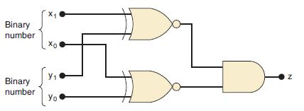
Data from Example 4-17
The notation x1x0 represents a two-bit binary number that can have any value (00, 01, 10, or 11); for example, when x1 = 1 and x0 = 0, the binary number is 10, and so on. Similarly, y1y0 represents another two-bit binary number. Design a logic circuit, using x1, x0, y1, and y0 inputs, whose output will be HIGH only when the two binary numbers x1x0 and y1y0 are equal.
Step by Step Answer:


Digital Systems Principles And Application
ISBN: 9780134220130
12th Edition
Authors: Ronald Tocci, Neal Widmer, Gregory Moss
