

For this problem, consider the single-line diagram for a building power system shown in Figure 8.34. In
Question:
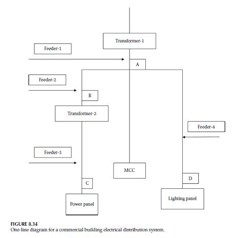
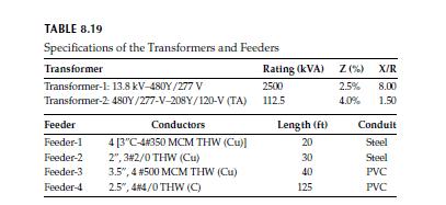
For this problem, consider the single-line diagram for a building power system shown in Figure 8.34. In particular, the utility system short-circuit kVA capability is 850,000 kVA with X/R = 6.0. Table 8.19 shows the impedance and X/R of the transformers. The purpose of this problem is to analyze the short-circuit currents at different locations of the system. Note that roof top A/C unit is basically an MCC panel. For all feeders, steel conduits are specified.
(a) Determine the short-circuit current at point A. Note that the main secondary feeder is 20 ft long with four parallel sets of 3 in. C-4#350 MCM THW (Cu).
(b) Determine the short-circuit current at point B just before Transformer-2 and point C at the power panel.
(c) Determine the short-circuit current at point D at the lighting panel.
(d) Based on this calculation, select the proper frame size and the trip rating for the circuit breakers of the main secondary and power panel as well as the lighting panel.
Step by Step Answer:


Energy Efficient Electrical Systems For Buildings
ISBN: 9781482258332
1st Edition
Authors: Moncef Krarti
