

Sketched in Fig. P12.6 are the upstream [section (1)] and downstream [section (2)] velocity triangles at the
Question:
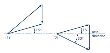
Sketched in Fig. P12.6 are the upstream [section (1)] and downstream [section (2)] velocity triangles at the arithmetic mean radius for flow through an axial-flow turbomachine rotor. The axial component of velocity is \(50 \mathrm{ft} / \mathrm{s}\) at sections (1) and (2).
(a) Label each velocity vector appropriately. Use \(\mathbf{V}\) for absolute velocity, \(\mathbf{W}\) for relative velocity, and \(\mathbf{U}\) for blade velocity.
(b) Are you dealing with a turbine or a fan?
(c) Calculate the work per unit mass involved.
(d) Sketch a reasonable blade section. Do you think that the actual blade exit angle will need to be less or greater than \(15^{\circ}\) ? Why?
Figure P12.6
Step by Step Answer:

This question has not been answered yet.
You can Ask your question!

Munson Young And Okiishi's Fundamentals Of Fluid Mechanics
ISBN: 9781119080701
8th Edition
Authors: Philip M. Gerhart, Andrew L. Gerhart, John I. Hochstein
