

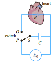
A heart pacemaker, shown in the following figure, consists of a switch, a battery, a capacitor, and
Question:
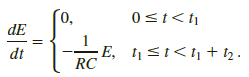
dE/dt = - 1/RC E.
(a) Let us assume that over the time interval of length t1, 0 < t < t1, the switch S is at position P shown in the following figure and the capacitor is being charged. When the switch is moved to position Q at time t1 the capacitor discharges, sending an impulse to the heart over the time interval of length t2: t1 ‰¤ t < t1 + t2. Thus over the initial charging/ discharging interval 0 < t < t1 + t2 the voltage to the heart is actually modeled by the piece wise-linear differential equation
By moving S between P and Q, the charging and discharging over time intervals of lengths t1 and t2 is repeated indefinitely.
Suppose t1 = 4 s, t2 = 2 s, E0 = 12 V, and E(0) = 0, E(4) = 12, E(6) = 0, E(10) = 12, E(12) = 0, and so on. Solve for E(t) for 0 ‰¤ t ‰¤ 24.
(b) Suppose for the sake of illustration that R = C = 1. Use a graphing utility to graph the solution for the IVP in part (a) for 0 ‰¤ t ‰¤ 24.
Step by Step Answer:
a For 0 t 4 6 t 10 and 12 t 16 no voltage is applied to the heart and Et 0 At the other tim...View the full answer


A First Course in Differential Equations with Modeling Applications
ISBN: 978-1305965720
11th edition
Authors: Dennis G. Zill
