

Sketch a structured multiblock grid with four sided elementary blocks for the computational domain of Prob. 1525.
Question:
Sketch a structured multiblock grid with four sided elementary blocks for the computational domain of Prob. 15–25. Each block is to have four-sided structured cells, but you do not have to sketch the grid, just the block topology. Try to make all the blocks as rectangular as possible to avoid highly skewed cells in the corners. Assume that the CFD code requires that the node distribution on periodic pairs of edges be identical (the two edges of a periodic pair are “linked” in the grid generation process). Also assume that the CFD code does not allow a block’s edges to be split for application of boundary conditions.
Data from Problem 15–25
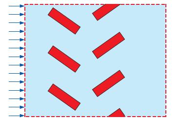
As a follow-up to the heat exchanger design of Prob. 15–22, suppose Anita’s design is chosen based on the results of a preliminary single-stage CFD analysis. Now she is asked to simulate two stages of the heat exchanger. The second row of rectangular tubes is staggered and inclined oppositely to that of the first row to promote mixing (Fig. P15–25). The geometry extends periodically up and down beyond the region shown here. Sketch a computational domain that can be used to simulate this flow. Label and indicate all boundary conditions on your diagram. Discuss.
FIGURE P15–25
Data from Problem 15-22
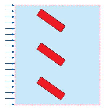
A new heat exchanger is being designed with the goal of mixing the fluid downstream of each stage as thoroughly as possible. Anita comes up with a design whose cross section for one stage is sketched in Fig. P15–22. The geometry extends periodically up and down beyond the region shown here. She uses several dozen rectangular tubes inclined at a high angle of attack to ensure that the flow separates and mixes in the wakes. The performance of this geometry is to be tested using two-dimensional time-averaged CFD simulations with a turbulence model, and the results will be compared to those of competing geometries. Sketch the simplest possible computational domain that can be used to simulate this flow. Label and indicate all boundary conditions on your diagram. Discuss.
FIGURE P15–22
Step by Step Answer:

This question has not been answered yet.
You can Ask your question!

Fluid Mechanics Fundamentals And Applications
ISBN: 9780073380322
3rd Edition
Authors: Yunus Cengel, John Cimbala
