

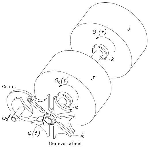
We analyzehere the model of the driving mechanism of the mechanism shown in Fig. 4.13, for p
Question:
We analyzehere the model of the driving mechanism of the mechanism shown in Fig. 4.13, forψp(t) given as
![Wp(t) = = 37, 3 (t - T) + arctan[f(t)], for 0](https://dsd5zvtm8ll6.cloudfront.net/images/question_images/1701/9/7/0/721657203210c4dc1701970720670.jpg)
Figure 4.13
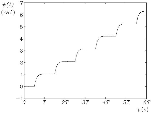
and displayed in Fig. 5.27, while f (t) is given, in turn, as
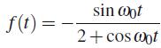
Figure 5.27
(a) Compute the coefficients of the first Nh harmonic components of the foregoing periodic function, by dividing the period in 2Nh intervals of equal length. Produce a table of error e in the Fourier approximation of ψp(t) vs. Nh, forNh = 1, 2, 3, 4, 5, 10, and 20. Comment on your tabulated results.
(b) Find the steady-state response of the system, i.e., θ1(t) and θ2(t), for Nh harmonics of the Fourier expansion of ψp(t). Choose the smallest value of Nh that will give you an error smaller than 0.05 in the approximation of ψp(t). Plot θ1(t) and θ2(t) vs. time in the [0, 4T] interval. Note that these plots are composed of a periodic and a nonperiodic part.
For the calculation, use the numerical values
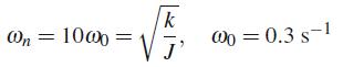
(c) In order to design the two shafts of the mechanism, we need the root-mean square value of the torque experienced by each shaft, which you are asked to provide. Find also the maximum absolute values of these torques.
Step by Step Answer:

This question has not been answered yet.
You can Ask your question!

Dynamic Response Of Linear Mechanical Systems Modeling Analysis And Simulation
ISBN: 9781461429463
1st Edition
Authors: Jorge Angeles
