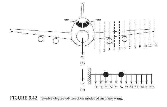
An airplane wing, Fig. 6.42(a), is modeled as a twelve-degree-of-freedom lumped-mass system as shown in Fig. 6.42(b).
Question:
An airplane wing, Fig. 6.42(a), is modeled as a twelve-degree-of-freedom lumped-mass system as shown in Fig. 6.42(b). The first three natural mode shapes, obtained experimentally, are given below.
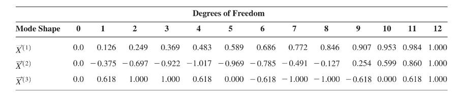
The natural frequencies corresponding to the three mode shapes are given by \(\omega_{1}=225 \mathrm{rad} / \mathrm{s}, \omega_{2}=660 \mathrm{rad} / \mathrm{s}\), and \(\omega_{3}=1100 \mathrm{rad} / \mathrm{s}\). If the fuselage of the airplane is subjected to a known vertical motion \(x_{0}(t)\), derive the uncoupled equations for determining the dynamic response of the wing by approximating it as a linear combination of the first three normal modes. Hint: The equation of motion of the airplane wing can be written, similar to Eq. (3.64), as \[[m] \ddot{\vec{x}}+[c]\left(\dot{\vec{x}}-\dot{x}_{0} \vec{u}_{1}\right)+[k]\left(\vec{x}-x_{0} \vec{u}_{1}\right)=\overrightarrow{0}\]
or \[[m] \ddot{\vec{x}}+[c] \dot{\vec{x}}+[k] \vec{x}=-x_{0}[m] \vec{u}_{1}\]
where \(\vec{u}_{1}=\{1,0,0, \ldots, 0\}^{T}\) is a unit vector.
Step by Step Answer: