

The crank in the slider-crank mechanism shown in Fig. 12.27 rotates at a constant clockwise angular speed
Question:
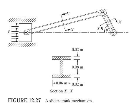
The crank in the slider-crank mechanism shown in Fig. 12.27 rotates at a constant clockwise angular speed of \(1000 \mathrm{rpm}\). Find the stresses in the connecting rod and the crank when the pressure acting on the piston is \(1 \mathrm{MPa}\) and \(\theta=30^{\circ}\). The diameter of the piston is \(0.3 \mathrm{~m}\) and the material of the mechanism is steel. Model the connecting rod and the crank by one beam element each. The lengths of the crank and connecting rod are \(0.3 \mathrm{~m}\) and \(1.2 \mathrm{~m}\), respectively.
Fantastic news! We've Found the answer you've been seeking!
Step by Step Answer:

Answered By
Shristi Singh
A freshman year metallurgy and material science student in India.
2+ Reviews
10+ Question Solved
Related Book For 
Question Posted:
