

The drilling machine shown in Fig. 5.29 (a) can be modeled as a two-degree-of-freedom system as indicated
Question:
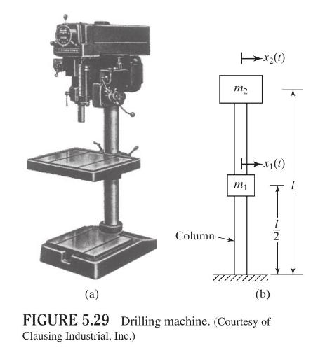
The drilling machine shown in Fig. 5.29 (a) can be modeled as a two-degree-of-freedom system as indicated in Fig. 5.29(b). Since a transverse force applied to mass \(m_{1}\) or mass \(m_{2}\) causes both the masses to deflect, the system exhibits elastic coupling. The bending stiffnesses of the column are given by (see Section 6.4 for the definition of stiffness influence coefficients)
\[k_{11}=\frac{768}{7} \frac{E I}{l^{3}}, \quad k_{12}=k_{21}=-\frac{240}{7} \frac{E I}{l^{3}}, \quad k_{22}=\frac{96}{7} \frac{E I}{l^{3}}\]
Determine the natural frequencies of the drilling machine.
Fantastic news! We've Found the answer you've been seeking!
Step by Step Answer:

Answered By
Muhammad Khurram
I have strong General Management skills to apply in your projects. Over last 3 years, I have acquired great knowledge of Accounting, Auditing, Microsoft Excel, Microsoft PowerPoint, Finance, Microsoft Project, Taxation, Strategic Management, Human Resource, Financial Planning, Business Planning, Microsoft Word, International Business, Entrepreneurship, General Management, Business Mathematics, Advertising, Marketing, Supply Chain, and E-commerce. I can guarantee professional services with accuracy.
249+ Reviews
407+ Question Solved
Related Book For 

Question Posted:
