

Modern mirrors, etalons, beam splitters, and other optical devices are generally made of glass or fused silica
Question:
Modern mirrors, etalons, beam splitters, and other optical devices are generally made of glass or fused silica (quartz) and have dielectric coatings on their surfaces. The coatings consist of alternating layers of materials with different dielectric constants, so the index of refraction n varies periodically. If, for example, the period of n’s variations is half a wavelength of the radiation, then waves reflected from successive dielectric layers build up coherently, producing a large net reflection coefficient; the result is a highly reflecting mirror.
In this exercise, we use a method due to Stokes to derive the reciprocity relations for devices with dielectric coatings, and in fact for much more general devices. Specifically, our derivation will be valid for locally plane-fronted, monochromatic waves impinging on an arbitrary, locally planar, lossless optical device.8 The device could be a mirror, a surface with an antireflection coating, an etalon, or any sequence of such objects with locally parallel surfaces.
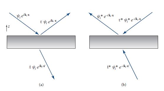
Let a plane, monochromatic wave ψieiki·xe−iωt impinge on the optical device from above, and orient the device so its normal is in the z direction and it is translation invariant in the x and y directions; see Fig. 9.8a. Then the reflected and transmitted waves are as shown in the figure. Because the medium below the device can have a different index of refraction from that above, the waves’ propagation direction below may be different from that above, as shown. For reasons explained in part (e), we denote position below the device by x' and position above the device by x. Some arbitrary choice has been made for the locations of the vertical origins z = 0 and z' = 0 on the two sides of the device.
(a) Consider a thought experiment in which the waves of Fig. 9.8a are time-reversed, so they impinge on the device from the original reflection and transmission directions and emerge toward the original input direction, as shown in Fig. 9.8b. If the device had been lossy, the time-reversed waves would not satisfy the field’s wave equation; the absence of losses guarantees they do. Show that mathematically, the time reversal can be achieved by complex conjugating the spatial part of the waves while leaving the temporal part e−iωt unchanged. Show, correspondingly, that the spatial part of the time-reversed waves is described by the formulas shown in Fig. 9.8b.
(b) Use the reflection and transmission coefficients to compute the waves produced by the inputs of Fig. 9.8b. From the requirement that the wave emerging from the device’s upward side must have the form shown in the figure, conclude that
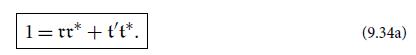
Similarly, from the requirement that no wave emerge from the device’s downward side, conclude that
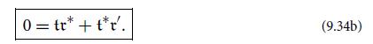
Eqs. (9.34) are the most general form of the reciprocity relations for lossless, planar devices.
(c) For a sharp interface between two homogeneous media, combine these general reciprocity relations with the ones derived in the text [Eqs. (9.32)] to show that t, t', r, and r' are all real.
(d) For the etalon of Figs. 9.6 and 9.7, re and te are given by Eqs. (9.33a). What do the reciprocity relations tell us about the coefficients for light propagating in the opposite direction, r'e and t'e?
(e) Show that for a general optical device, the reflection and transmission coefficients can all be made real by appropriate, independent adjustments of the origins of the vertical coordinates z (for points above the device) and z' (for points below the device). More specifically, show that by setting znew = zold + δz and z'new = z'old + δz' and choosing δz and δz' appropriately, one can make t and r real. Show further that the reciprocity relations (9.34a) and (9.34b) then imply that t' and r' are also real. Finally, show that this adjustment of origins brings the real reciprocity relations into the same form (9.32) as for a sharp interface between two homogeneous media.
As attractive as it may be to have these coefficients real, one must keep in mind some disadvantages:
(i) The displaced origins for z and z' in general will depend on frequency, and correspondingly,
(ii) Frequency-dependent information (most importantly, frequency-dependent phase shifts of the light) is lost by making the coefficients real. If the phase shifts depend only weakly on frequency over the band of interest (as is typically the case for the dielectric coating of a mirror face), then these disadvantages are unimportant and it is conventional to choose the coefficients real. If the phase shifts depend strongly on frequency over the band of interest [e.g., for the etalon of Eqs. (9.33a), when its two faces are highly reflecting and its round-trip phase φ is near a multiple of 2π], the disadvantages are severe. One then should leave the origins frequency independent, and correspondingly leave the device’s r, r', t, and t' complex [as we have for the etalon in Eqs. (9.33a)].
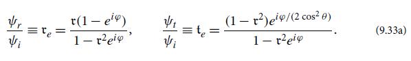
FIGURE 9.6.
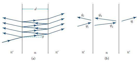
FIGURE 9.7.
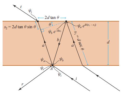
FIGURE 9.8
Step by Step Answer:


Modern Classical Physics Optics Fluids Plasmas Elasticity Relativity And Statistical Physics
ISBN: 9780691159027
1st Edition
Authors: Kip S. Thorne, Roger D. Blandford
