

Consider the circuit of Figure 1. Assume that the capacitor is short for AC signals and open
Question:
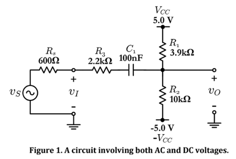
Consider the circuit of Figure 1. Assume that the capacitor is short for AC signals and open for DC signals. Also, assume that voltage vs in Figure 1 is a 20-kHz sinusoid with a peak-to-peak swing of 4.0 V (or, equivalently, with an rms value of 1.41 V). Thus, let vs(t) = 2s1n(art), where = 2ir x 20,000 rod/s. Then, use the "superposition principle to manually find the waveforms of voltages vt and vo (i.e., the time functions vi(t) and vo(t)). Use Matlab or Excel to plot your expressions for vi(t) and vo(t), for two cycles (periods), and present the result as Graph Pl. Also, complete Table P1 based on your calculations. See the Reminder below. Show all work.
Hint
Superposition can be exercised in various ways. For example, one way would be to consider the response of a circuit as the sum of the response due to the AC sources (while the DC sources are-or) and the response due to the DC sources (while the AC sources are -on. Remember that, regardless of AC or DC, an -or voltage source means a short link, whereas an -or current source means an open circuit.
Reminder:
The "DC" value (also known as the "average" of "mean") of a periodic waveform v(t) is defined by the following integral:

Where T is the period of the waveform. All meters in their DC measurement model display the DC or average value of the incoming signal.
The "rms" value of v(t), is defined by the following integral
 Which is the square root of the average of the square of the waveform' Modern meters in their AC measurement mode display the rms value of the incoming signal, as defined by the above Integral. A very famous special case, which is often incorrectly generalized, is that of a sinusoidal waveform: The rms value of a sinusoid is V rms = V m /?2, where V m is the peak value of the sinusoid.
Many modern meters are also capable of doing the so-called AC+DC measurements. In its AC + DC measurement mode a meter can calculate the rms value of a waveform that consists Ma DC component and an AC component Thus, the meter displays the following:
 where:
V dc : The DC (average) component of v(t), which the meter displays in its DC measurement mode.
V rms : The rms value of the AC component of v(t), which the meter displays in its AC measurement mode.
V RMS : The rms value of v(t) as a whole, which the meter displays in its AC+DC measurement mode.
In the discussion above, we used v(t) to symbolize a signal. However, the discussion applies to any signal in general, irrespective of its physical nature, voltage, current, etc.

Expert Answer:
Assumption Capacity is short for AC signals and open for DC signals Superposition th... View the full answer


Fundamentals of Electric Circuits
ISBN: 9780073301150
3rd edition
Authors: Matthew Sadiku, Charles Alexander
