The attitude-control system of a space booster is shown in Figure (a). The attitude angle ? is
Question:
The attitude-control system of a space booster is shown in Figure (a). The attitude angle ? is controlled by controlling the engine angle ?, which is then the angle of the applied thrust, FT. The vehicle velocity is denoted by v. These control systems are sometimes open-loop unstable, which occurs if the center of aerodynamic pressure is forward of the booster center of gravity. For example, the rigid-body transfer function of the Saturn V booster was 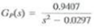
This transfer function does not include vehicle bending dynamics, liquid fuel slosh dynamics, or the dynamics of the hydraulic motor that positioned the engine. These dynamics added 25 orders to the transfer function. The rigid-body vehicle was stabilized by the addition of rate feedback, as shown in Figure. (Rate feedback, in addition to other types of compensation, was used on the actual vehicle.) (a) Let Kp = 0. Plot the root locus and state the different types of (nonslable) responses possible. (b) Replace Kp with a compensator with the transfer function Gc(s). Based on the root locus of (a), which types of compensators can be employed to stabilize the closed-loop system? (c) Design a phase-lead compensator with a dc gain of 0.1 that places a closed-loop pole at s = -0.25 +j0.25.
(d) Use MATLAB to verify the closed-loop poles in (c).
(e) Use SIMULINK to verify the system time constant in (c). 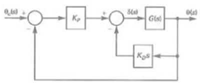
Expert Answer:
a Refer to FIGURE P729 a in the textbook Consider the given plant transfer function Consider the overall transfer function Gs K P G P s 2 Substitute Equation 1 in Equation 2 Consider the general form ... View the full answer