

A black square means that the associated shafts are lifted, so the process is as follows: Lift
Question:
A black square means that the associated shafts are lifted, so the process is as follows:
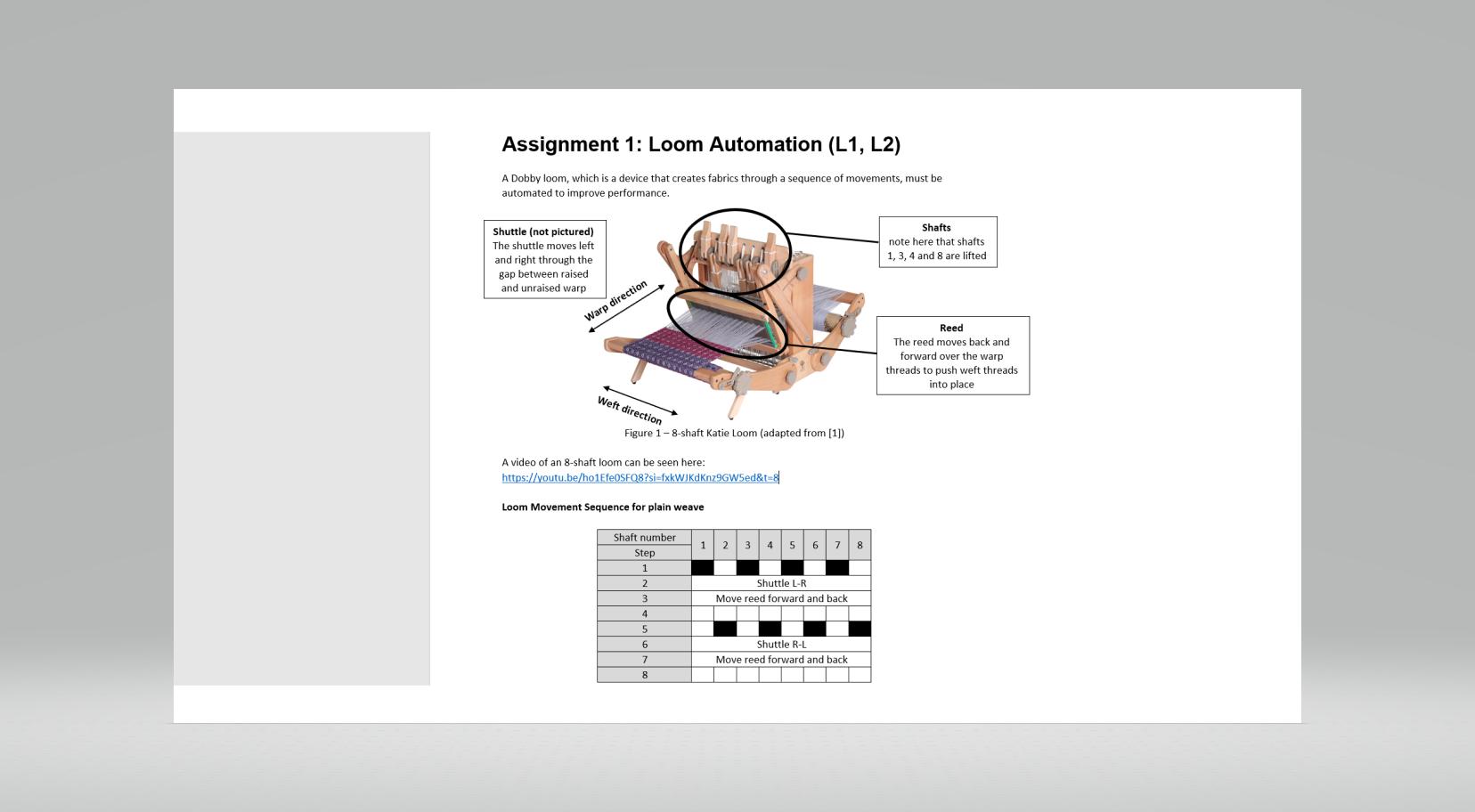
- Lift all odd shafts
- Slide the bobbin shuttle through the gap in the warp threads
- Move the reed forward and back to secure the weft thread position
- Lower all odd shafts
- Raise all even number shafts
- Slide the bobbin shuttle through the gap in the warp threads
- Move the reed forward and back to secure the weft thread position
- Lower all even shafts
This 8-step process can be repeated for a long as required to create a fabric which has a “plain” weave pattern. Other patterns can be achieved by changing the shaft combinations in the process.
Automation
To automate the system, switches and sensors will be used to detect the simulated movement of the loom. Switches will be used to simulate the shaft position and either a switch or light sensors will be used to simulate the shuttle position
There is also a fault sensor, which checks shaft and shuttle inputs and, if a fault is detected, then a warning light will flash to denote a fault state. Please note faults can also be detected by an unexpected combination of the inputs.
You will design this system using KL46Z as the microcontroller to control the above operation. Write a C program that allows a KL46Z to read the values from all sensors and to control the status of the loom.
The map of the inputs and outputs is:
Use eight “D” pins for shaft positions
Use two “D” pins for shuttle position
A rocker switch to represent the reed moving forward and back
Use an additional “D” pin for fault sensor S3 (1 bit) (if needed)
Use the two onboard LEDs to display the shuttle position (left and right)
Use additional LEDs (with current-limiting resistors) attached to outputs on the board to represent the other states
There should be no condition where the shuttle can move while the shafts position is incorrect
Additional (optional features):
- Use the segment display on the board to provide more information (state, shafts selected, error condition etc)
- Use the on-board light sensor to represent the shuttle position
- Use the on-board accelerometer to represent the shuttle position
- Use of any other on-board sensor to better represent the loom process
- Take in a more complex shaft pattern for 8-shaft loom which can run through a more complex pattern process (This would involve inputting a csv file of the right format and representing lifted shafts with LEDs, to guide the switch positions)
Marking components
Assignment 1 submission (100%) will consist of two parts: A (70%) and B (30%) as follows:
The Assignment Report (items 1-4 below) with total mark will be 70%:
Describe problem specification and full system block diagram (10%)
- Input – 5%
- Output – 5%
State diagram with comments (25%)
- State diagram - 15%
- Explanation and Comments - 10%
Code with comments (25%)
- Inputs for shafts, shuttles and reed working correctly – 5%
- Sequence changing correctly – 5%
- Adequate visual representation of state/positions (LED for shafts, clear current state)– 5%
- Fault condition (either from dedicated switch, detecting an unknown combination of inputs or both)– 5%
- Using function for each state – 5%
- Additional Features (10%)
- As mentioned above of other useful additional functionality
Practical demonstration (30%)
A 3-minute video demonstrating the system operation is required. In the video, you need to show the full sequences mentioned above
In the video you need to demonstrate:
- Sensor value reading – shaft, shuttle and reed position (5%)
- The correct pattern of the shaft position for a “plain” weave (5%)
- A fault condition (5%)
- Any addition features you have included (5%)
Video marking will be based on the above sections will give 20% in total. The remaining 10% will be awarded based on the quality of video and presentation (clear and sufficient). It is advised that you can prepare a written transcript beforehand.
- In the recording, you need to say your name, talk /explain the system operation and record yourself as a part of the video. The video length is strictly 3 minutes. If the video is more than 3 mins, only the first 3 mins will be marked. The video size should be reasonably small up to 50 MB.
- You need to use KL46Z board, prototype breadboard, LEDs and wires to build the system and record the video.
- A copied or shared video is NOT allowed and marked as academic misconduct*. Each student should record their own video.
These will both be submitted via eLP, one submission for the video and one for the report, which will be checked in Turnitin.
(*) The assignment is an individual work. Please make sure it is your own work and do not share to other students in any form. An academic misconduct case will be raised if plagiarism or collusion is suspected.
[1] https://www.weaversmith.co.uk/wp-content/uploads/2018/08/KTL_2015_web.jpg
Expert Answer:
Creating a complete C program for the KL46Z microcontroller along with the required documentation de... View the full answer


Auditing A Practical Approach with Data Analytics
ISBN: 978-1119401742
1st edition
Authors: Raymond N. Johnson, Laura Davis Wiley, Robyn Moroney, Fiona Campbell, Jane Hamilton
