

A wind tunnel installation used to control motion of an aerofoil is described in Figure 1...
Fantastic news! We've Found the answer you've been seeking!
Question:
Transcribed Image Text:
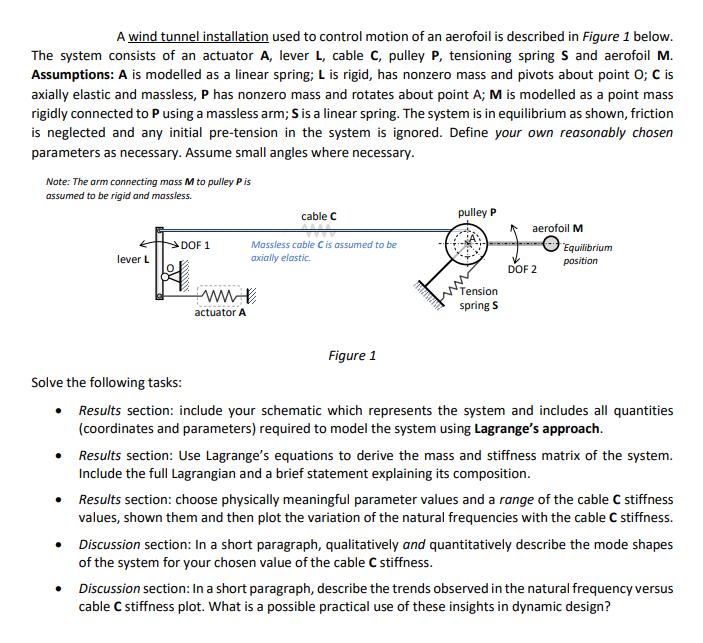
A wind tunnel installation used to control motion of an aerofoil is described in Figure 1 below. The system consists of an actuator A, lever L, cable C, pulley P, tensioning spring S and aerofoil M. Assumptions: A is modelled as a linear spring; L is rigid, has nonzero mass and pivots about point O; C is axially elastic and massless, P has nonzero mass and rotates about point A; M is modelled as a point mass rigidly connected to P using a massless arm; S is a linear spring. The system is in equilibrium as shown, friction is neglected and any initial pre-tension in the system is ignored. Define your own reasonably chosen parameters as necessary. Assume small angles where necessary. Note: The arm connecting mass M to pulley P is assumed to be rigid and massless. lever L DOF 1 . ww actuator A cable C Massless cable C is assumed to be axially elastic. Figure 1 AMAHAHA pulley P Tension spring S aerofoil M DOF 2 Equilibrium position Solve the following tasks: Results section: include your schematic which represents the system and includes all quantities (coordinates and parameters) required to model the system using Lagrange's approach. • Results section: Use Lagrange's equations to derive the mass and stiffness matrix of the system. Include the full Lagrangian and a brief statement explaining its composition. Results section: choose physically meaningful parameter values and a range of the cable C stiffness values, shown them and then plot the variation of the natural frequencies with the cable C stiffness. • Discussion section: In a short paragraph, qualitatively and quantitatively describe the mode shapes of the system for your chosen value of the cable C stiffness. • Discussion section: In a short paragraph, describe the trends observed in the natural frequency versus cable C stiffness plot. What is a possible practical use of these insights in dynamic design? A wind tunnel installation used to control motion of an aerofoil is described in Figure 1 below. The system consists of an actuator A, lever L, cable C, pulley P, tensioning spring S and aerofoil M. Assumptions: A is modelled as a linear spring; L is rigid, has nonzero mass and pivots about point O; C is axially elastic and massless, P has nonzero mass and rotates about point A; M is modelled as a point mass rigidly connected to P using a massless arm; S is a linear spring. The system is in equilibrium as shown, friction is neglected and any initial pre-tension in the system is ignored. Define your own reasonably chosen parameters as necessary. Assume small angles where necessary. Note: The arm connecting mass M to pulley P is assumed to be rigid and massless. lever L DOF 1 . ww actuator A cable C Massless cable C is assumed to be axially elastic. Figure 1 AMAHAHA pulley P Tension spring S aerofoil M DOF 2 Equilibrium position Solve the following tasks: Results section: include your schematic which represents the system and includes all quantities (coordinates and parameters) required to model the system using Lagrange's approach. • Results section: Use Lagrange's equations to derive the mass and stiffness matrix of the system. Include the full Lagrangian and a brief statement explaining its composition. Results section: choose physically meaningful parameter values and a range of the cable C stiffness values, shown them and then plot the variation of the natural frequencies with the cable C stiffness. • Discussion section: In a short paragraph, qualitatively and quantitatively describe the mode shapes of the system for your chosen value of the cable C stiffness. • Discussion section: In a short paragraph, describe the trends observed in the natural frequency versus cable C stiffness plot. What is a possible practical use of these insights in dynamic design? A wind tunnel installation used to control motion of an aerofoil is described in Figure 1 below. The system consists of an actuator A, lever L, cable C, pulley P, tensioning spring S and aerofoil M. Assumptions: A is modelled as a linear spring; L is rigid, has nonzero mass and pivots about point O; C is axially elastic and massless, P has nonzero mass and rotates about point A; M is modelled as a point mass rigidly connected to P using a massless arm; S is a linear spring. The system is in equilibrium as shown, friction is neglected and any initial pre-tension in the system is ignored. Define your own reasonably chosen parameters as necessary. Assume small angles where necessary. Note: The arm connecting mass M to pulley P is assumed to be rigid and massless. lever L DOF 1 . ww actuator A cable C Massless cable C is assumed to be axially elastic. Figure 1 AMAHAHA pulley P Tension spring S aerofoil M DOF 2 Equilibrium position Solve the following tasks: Results section: include your schematic which represents the system and includes all quantities (coordinates and parameters) required to model the system using Lagrange's approach. • Results section: Use Lagrange's equations to derive the mass and stiffness matrix of the system. Include the full Lagrangian and a brief statement explaining its composition. Results section: choose physically meaningful parameter values and a range of the cable C stiffness values, shown them and then plot the variation of the natural frequencies with the cable C stiffness. • Discussion section: In a short paragraph, qualitatively and quantitatively describe the mode shapes of the system for your chosen value of the cable C stiffness. • Discussion section: In a short paragraph, describe the trends observed in the natural frequency versus cable C stiffness plot. What is a possible practical use of these insights in dynamic design? A wind tunnel installation used to control motion of an aerofoil is described in Figure 1 below. The system consists of an actuator A, lever L, cable C, pulley P, tensioning spring S and aerofoil M. Assumptions: A is modelled as a linear spring; L is rigid, has nonzero mass and pivots about point O; C is axially elastic and massless, P has nonzero mass and rotates about point A; M is modelled as a point mass rigidly connected to P using a massless arm; S is a linear spring. The system is in equilibrium as shown, friction is neglected and any initial pre-tension in the system is ignored. Define your own reasonably chosen parameters as necessary. Assume small angles where necessary. Note: The arm connecting mass M to pulley P is assumed to be rigid and massless. lever L DOF 1 . ww actuator A cable C Massless cable C is assumed to be axially elastic. Figure 1 AMAHAHA pulley P Tension spring S aerofoil M DOF 2 Equilibrium position Solve the following tasks: Results section: include your schematic which represents the system and includes all quantities (coordinates and parameters) required to model the system using Lagrange's approach. • Results section: Use Lagrange's equations to derive the mass and stiffness matrix of the system. Include the full Lagrangian and a brief statement explaining its composition. Results section: choose physically meaningful parameter values and a range of the cable C stiffness values, shown them and then plot the variation of the natural frequencies with the cable C stiffness. • Discussion section: In a short paragraph, qualitatively and quantitatively describe the mode shapes of the system for your chosen value of the cable C stiffness. • Discussion section: In a short paragraph, describe the trends observed in the natural frequency versus cable C stiffness plot. What is a possible practical use of these insights in dynamic design?
Expert Answer:

Related Book For 

Posted Date:
Students also viewed these accounting questions
-
ACCORDING TO PROJECT MANAGEMENT PROJECT CHANGE, WHAT CHANGE IS REQUIRED FOR THIS CASE STUDY, JUSTIFY THE CHANGE BY APPLYING THE TOOLS AND TECHNIQUES FROM QUALITY MANAGEMENT IN IDENTIFYING THE ROOT...
-
Managing Scope Changes Case Study Scope changes on a project can occur regardless of how well the project is planned or executed. Scope changes can be the result of something that was omitted during...
-
What is the result of executing the following method? A. The declaration of name does not compile. B. The declaration of _number does not compile. C. The declaration of profit$$$ does not compile. D....
-
Write the formula for the price elasticity of demand. Why isn't elasticity just measured by the slope of the demand curve?
-
Consider the following network, where each number along a link represents the actual distance between the pair of nodes connected by that link. The objective is to find the shortest path from the...
-
Explain the significance of collection class and provide two examples.
-
Calculate financial leverage measures. The following information was available for the year ended December 31, 2013: Earnings before interest and taxes (operating income) ....... $60,000 Interest...
-
The carrying case would be sold to the end consumer for $ 4 9 . 9 9 . Lisa will not sell directly to the consumer but will use a wholesaler who will sell to a retailer ( e . g . , university...
-
Part I of this case, presented in Chapter 3, discussed the situation of D'Leon Inc., a regional snack foods producer, after an expansion program. D'Leon had increased plant capacity and undertaken a...
-
A person wants to design a weekly exercise program with the following three sports: CrossFit, cycling, and swimming. The person would like to invest at least as much time cycling as doing CrossFit...
-
1. Evaluate the integral S L cos (2) dx dy 2y by reversing the order of integration.
-
Given the Volumetric Analysis of a Natural Gas: CH4 = 67.3% Nitrogen = 9.6% 0 = 2.7% CO = 0.8% CH6 = 15.4% CO = 1.8% H = 2.4% Calculate the A/F ratio by mass considering CO = 10.8% CO2. Note: Use...
-
Figure Q4a illustrates a two-dimensional boundary-layer velocity profile over a flat wall. The sketch identifies flow velocities U, i = 1...5 at five successive heights spaced Ay apart and the...
-
PROBLEM 1 Class Workshop Exercise: Consider a person strengthening the shoulder muscles by means of dumbbell exercises. The figure bellow illustrates the position of the left arm when the arm is...
-
1. The input variable of mechanism in the Figure is 012. BD is perpendicular to DC. a) Write vector loop closure equation of mechanism. Write vector loop of closure equation in complex numbers. b) In...
-
Calculate semi-monthly net pay:
-
Estimate a range for the optimal objective value for the following LPs: (a) Minimize z = 5x1 + 2x2 Subject to X1 - x2 3 2x1 + 3x2 5 X1, x2 0 (b) Maximize z = x1 + 5x2 + 3x3 Subject to X1 + 2x2 +...
-
Evaluate the determinants 3 2 6 5 and 24 68 2 5 4 -1 3
-
Determine the horizontal displacement of joint D. AE is constant. Use the principle of virtual work. 6 kN A ID 3 m. Ic 3 m B -6 kN Probs. F8-5/6
-
Solve Prob. 710 using the conjugate-beam method. Data from Prob. 710 Determine the slope at B and the maximum displacement of the beam. Use the moment-area theorems. Take E = 200 GPa, I = 550(10 6 )...
-
Why should projects be linked to the organisation's Strategic Plan?
-
What is the BCG matrix and how is it used?
-
Explain the role projects play in the delivery of an organisation's strategy

Study smarter with the SolutionInn App