

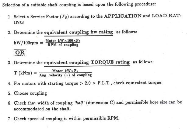
Selection of a suitable shaft coupling is based upon the following procedure: 1. Select a Service...
Fantastic news! We've Found the answer you've been seeking!
Question:
Transcribed Image Text:
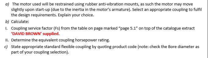
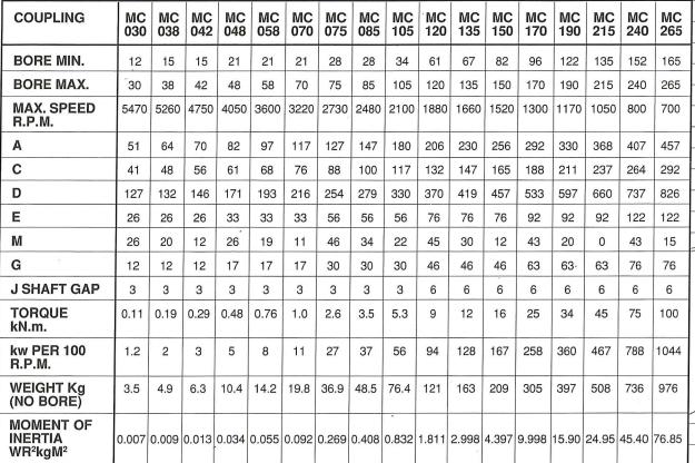
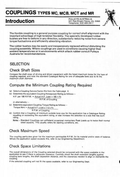
Selection of a suitable shaft coupling is based upon the following procedure: 1. Select a Service Factor (Fs) according to the APPLICATION and LOAD RAT- ING 2. Determine the equivalent coupling kw rating as follows: Motor kWx100x Fs kW/100rpm RPM of coupling OR 3. Determine the equivalent coupling TORQUE rating as follows: Motor kWxFs T (kNm): Ang. velocity (w) of coupling 4. For motors with starting torque > 2.0 x F.L.T., check equivalent torque. 5. Choose coupling 6. Check that width of coupling 'half' (dimension C) and permissible bore size can be accommodated on the shaft. 7. Check speed of coupling is within permissible RPM. a) The motor used will be restrained using rubber anti-vibration mounts, as such the motor may move slightly upon start-up (due to the inertia in the motor's armature). Select an appropriate coupling to fulfil the design requirements. Explain your choice. b) Calculate: 1. Coupling service factor (Fs) from the table on page marked "page 5.1" on top of the catalogue extract 'DAVID BROWN' supplied. II. Determine the equivalent coupling horsepower rating. c) State appropriate standard flexible coupling by quoting product code (note: check the Bore diameter as part of your coupling selection). COUPLING BORE MIN. BORE MAX. MAX. SPEED R.P.M. A C D E M G J SHAFT GAP TORQUE kN.m. kw PER 100 R.P.M. WEIGHT Kg (NO BORE) MOMENT OF INERTIA WR²kgM² MC MC MC MC MC MC MC MC MC MC MC MC MC MC MC MC MC 030 038 042 048 058 070 075 085 105 120 135 150 170 190 215 240 265 12 15 15 21 21 21 67 82 96 122 135 152 165 28 28 34 61 70 75 85 105 120 135 150 170 190 215 240 265 30 38 42 48 58 5470 5260 4750 4050 3600 3220 2730 2480 2100 1880 1660 1520 1300 1170 1050 800 700 51 64 70 41 48 82 97 117 127 68 76 88 216 254 127 132 146 193 26 26 26 33 33 33 56 26 20 12 26 19 11 46 12 12 12 17 17 17 30 3 3 3 3 3 3 3 0.11 0.19 0.29 0.48 0.76 56 61 171 29 1.0 2.6 147 180 206 230 256 292 330 100 117 132 147 165 188 211 279 330 370 419 457 533 597 76 92 92 56 56 76 76 34 22 45 30 12 43 20 30 30 46 46 46 63 6 6 6 3 3 6 3.5 5.3 9 12 16 25 368 407 457 237 264 292 660 737 826 92 122 122 0 63- 63 6 34 43 15 76 76 6 6 6 45 75 100 1.2 2 3 5 8 11 27 37 56 94 128 167 258 360 467 788 1044 3.5 4.9 6.3 10.4 14.2 19.8 36.9 48.5 76.4 121 163 209 305 397 508 736 976 0.007 0.009 0.013 0.034 0.055 0.092 0.269 0.408 0.832 1.811 2.998 4.397 9.998 15.90 24.95 45.40 76.85 COUPLINGS TYPES MC, MCB, MCT and MR Introduction PULLEYS AUSTRALIA 501 Rae Street, Fitzroy, Vic, 3068 Telephone: (03) 489 2877 The flexible coupling is a general purpose coupling for correct shaft alignment with the important advantage of high torsional flexibility. The specially developed rubber bushes are free to deform in any direction, substantially reducing noise from severe torque fluctuations and efficiently absorbing vibration. The rubber bushes may be easily and inexpensively replaced without disturbing the coupling assembly. Where couplings are used in conditions causing higher than ambient temperatures or in environments which attack rubber consult Pulleys Australia for recommendations. SELECTION Check Shaft Sizes Compare the shaft sizes of driving and driven equipment with the listed maximum bores for the type of coupling required, and note the standard Catalogue Rating for one of adequate bore size to fit the maximum shaft diameter. Compute the Minimum Coupling Rating Required (a) Select a Coupling Service Factor (Fs from the Table page 4. (b) Determine the equivalent Coupling Horsepower Rating as follows:- H.P. per 100 R.P.M. Actual HP. Load x 100 x Fs R.P.M. of Coupling or alternatively: (c) Determine equivalent Coupling Torque Rating as follows:- Torque (Nm) Actual H.P. Load x 7.12 x Fs R.P.M. of Coupling (d) Confirm that a Coupling of minimum suitable bore size for the application has a Catalogue Rating equalling or exceeding the equivalent rating, or else increase the selection to a size that has such rating. Note: Standard Couplings can withstand occasional momentary Peak Loads up to twice their normal rated capacity. This usually caters for starting conditions, etc. Check Maximum Speed The coupling particulars given list the maximum permissible R.P.M. for its material and/or state of balance. Where the application speed exceeds this, refer to our Engineering Department Check Space Limitations The overall dimensions of the Coupling selected should be compared with the space available in the application to see if there is adequate clearance. Carefully check the shaft extension lengths against coupling bore lengths, the shaft separation distance, and the clearances needed to align or dismantle the coupling If the selected coupling will not fit the space available, refer to our Engineering Dept Selection of a suitable shaft coupling is based upon the following procedure: 1. Select a Service Factor (Fs) according to the APPLICATION and LOAD RAT- ING 2. Determine the equivalent coupling kw rating as follows: Motor kWx100x Fs kW/100rpm RPM of coupling OR 3. Determine the equivalent coupling TORQUE rating as follows: Motor kWxFs T (kNm): Ang. velocity (w) of coupling 4. For motors with starting torque > 2.0 x F.L.T., check equivalent torque. 5. Choose coupling 6. Check that width of coupling 'half' (dimension C) and permissible bore size can be accommodated on the shaft. 7. Check speed of coupling is within permissible RPM. a) The motor used will be restrained using rubber anti-vibration mounts, as such the motor may move slightly upon start-up (due to the inertia in the motor's armature). Select an appropriate coupling to fulfil the design requirements. Explain your choice. b) Calculate: 1. Coupling service factor (Fs) from the table on page marked "page 5.1" on top of the catalogue extract 'DAVID BROWN' supplied. II. Determine the equivalent coupling horsepower rating. c) State appropriate standard flexible coupling by quoting product code (note: check the Bore diameter as part of your coupling selection). COUPLING BORE MIN. BORE MAX. MAX. SPEED R.P.M. A C D E M G J SHAFT GAP TORQUE kN.m. kw PER 100 R.P.M. WEIGHT Kg (NO BORE) MOMENT OF INERTIA WR²kgM² MC MC MC MC MC MC MC MC MC MC MC MC MC MC MC MC MC 030 038 042 048 058 070 075 085 105 120 135 150 170 190 215 240 265 12 15 15 21 21 21 67 82 96 122 135 152 165 28 28 34 61 70 75 85 105 120 135 150 170 190 215 240 265 30 38 42 48 58 5470 5260 4750 4050 3600 3220 2730 2480 2100 1880 1660 1520 1300 1170 1050 800 700 51 64 70 41 48 82 97 117 127 68 76 88 216 254 127 132 146 193 26 26 26 33 33 33 56 26 20 12 26 19 11 46 12 12 12 17 17 17 30 3 3 3 3 3 3 3 0.11 0.19 0.29 0.48 0.76 56 61 171 29 1.0 2.6 147 180 206 230 256 292 330 100 117 132 147 165 188 211 279 330 370 419 457 533 597 76 92 92 56 56 76 76 34 22 45 30 12 43 20 30 30 46 46 46 63 6 6 6 3 3 6 3.5 5.3 9 12 16 25 368 407 457 237 264 292 660 737 826 92 122 122 0 63- 63 6 34 43 15 76 76 6 6 6 45 75 100 1.2 2 3 5 8 11 27 37 56 94 128 167 258 360 467 788 1044 3.5 4.9 6.3 10.4 14.2 19.8 36.9 48.5 76.4 121 163 209 305 397 508 736 976 0.007 0.009 0.013 0.034 0.055 0.092 0.269 0.408 0.832 1.811 2.998 4.397 9.998 15.90 24.95 45.40 76.85 COUPLINGS TYPES MC, MCB, MCT and MR Introduction PULLEYS AUSTRALIA 501 Rae Street, Fitzroy, Vic, 3068 Telephone: (03) 489 2877 The flexible coupling is a general purpose coupling for correct shaft alignment with the important advantage of high torsional flexibility. The specially developed rubber bushes are free to deform in any direction, substantially reducing noise from severe torque fluctuations and efficiently absorbing vibration. The rubber bushes may be easily and inexpensively replaced without disturbing the coupling assembly. Where couplings are used in conditions causing higher than ambient temperatures or in environments which attack rubber consult Pulleys Australia for recommendations. SELECTION Check Shaft Sizes Compare the shaft sizes of driving and driven equipment with the listed maximum bores for the type of coupling required, and note the standard Catalogue Rating for one of adequate bore size to fit the maximum shaft diameter. Compute the Minimum Coupling Rating Required (a) Select a Coupling Service Factor (Fs from the Table page 4. (b) Determine the equivalent Coupling Horsepower Rating as follows:- H.P. per 100 R.P.M. Actual HP. Load x 100 x Fs R.P.M. of Coupling or alternatively: (c) Determine equivalent Coupling Torque Rating as follows:- Torque (Nm) Actual H.P. Load x 7.12 x Fs R.P.M. of Coupling (d) Confirm that a Coupling of minimum suitable bore size for the application has a Catalogue Rating equalling or exceeding the equivalent rating, or else increase the selection to a size that has such rating. Note: Standard Couplings can withstand occasional momentary Peak Loads up to twice their normal rated capacity. This usually caters for starting conditions, etc. Check Maximum Speed The coupling particulars given list the maximum permissible R.P.M. for its material and/or state of balance. Where the application speed exceeds this, refer to our Engineering Department Check Space Limitations The overall dimensions of the Coupling selected should be compared with the space available in the application to see if there is adequate clearance. Carefully check the shaft extension lengths against coupling bore lengths, the shaft separation distance, and the clearances needed to align or dismantle the coupling If the selected coupling will not fit the space available, refer to our Engineering Dept Selection of a suitable shaft coupling is based upon the following procedure: 1. Select a Service Factor (Fs) according to the APPLICATION and LOAD RAT- ING 2. Determine the equivalent coupling kw rating as follows: Motor kWx100x Fs kW/100rpm RPM of coupling OR 3. Determine the equivalent coupling TORQUE rating as follows: Motor kWxFs T (kNm): Ang. velocity (w) of coupling 4. For motors with starting torque > 2.0 x F.L.T., check equivalent torque. 5. Choose coupling 6. Check that width of coupling 'half' (dimension C) and permissible bore size can be accommodated on the shaft. 7. Check speed of coupling is within permissible RPM. a) The motor used will be restrained using rubber anti-vibration mounts, as such the motor may move slightly upon start-up (due to the inertia in the motor's armature). Select an appropriate coupling to fulfil the design requirements. Explain your choice. b) Calculate: 1. Coupling service factor (Fs) from the table on page marked "page 5.1" on top of the catalogue extract 'DAVID BROWN' supplied. II. Determine the equivalent coupling horsepower rating. c) State appropriate standard flexible coupling by quoting product code (note: check the Bore diameter as part of your coupling selection). COUPLING BORE MIN. BORE MAX. MAX. SPEED R.P.M. A C D E M G J SHAFT GAP TORQUE kN.m. kw PER 100 R.P.M. WEIGHT Kg (NO BORE) MOMENT OF INERTIA WR²kgM² MC MC MC MC MC MC MC MC MC MC MC MC MC MC MC MC MC 030 038 042 048 058 070 075 085 105 120 135 150 170 190 215 240 265 12 15 15 21 21 21 67 82 96 122 135 152 165 28 28 34 61 70 75 85 105 120 135 150 170 190 215 240 265 30 38 42 48 58 5470 5260 4750 4050 3600 3220 2730 2480 2100 1880 1660 1520 1300 1170 1050 800 700 51 64 70 41 48 82 97 117 127 68 76 88 216 254 127 132 146 193 26 26 26 33 33 33 56 26 20 12 26 19 11 46 12 12 12 17 17 17 30 3 3 3 3 3 3 3 0.11 0.19 0.29 0.48 0.76 56 61 171 29 1.0 2.6 147 180 206 230 256 292 330 100 117 132 147 165 188 211 279 330 370 419 457 533 597 76 92 92 56 56 76 76 34 22 45 30 12 43 20 30 30 46 46 46 63 6 6 6 3 3 6 3.5 5.3 9 12 16 25 368 407 457 237 264 292 660 737 826 92 122 122 0 63- 63 6 34 43 15 76 76 6 6 6 45 75 100 1.2 2 3 5 8 11 27 37 56 94 128 167 258 360 467 788 1044 3.5 4.9 6.3 10.4 14.2 19.8 36.9 48.5 76.4 121 163 209 305 397 508 736 976 0.007 0.009 0.013 0.034 0.055 0.092 0.269 0.408 0.832 1.811 2.998 4.397 9.998 15.90 24.95 45.40 76.85 COUPLINGS TYPES MC, MCB, MCT and MR Introduction PULLEYS AUSTRALIA 501 Rae Street, Fitzroy, Vic, 3068 Telephone: (03) 489 2877 The flexible coupling is a general purpose coupling for correct shaft alignment with the important advantage of high torsional flexibility. The specially developed rubber bushes are free to deform in any direction, substantially reducing noise from severe torque fluctuations and efficiently absorbing vibration. The rubber bushes may be easily and inexpensively replaced without disturbing the coupling assembly. Where couplings are used in conditions causing higher than ambient temperatures or in environments which attack rubber consult Pulleys Australia for recommendations. SELECTION Check Shaft Sizes Compare the shaft sizes of driving and driven equipment with the listed maximum bores for the type of coupling required, and note the standard Catalogue Rating for one of adequate bore size to fit the maximum shaft diameter. Compute the Minimum Coupling Rating Required (a) Select a Coupling Service Factor (Fs from the Table page 4. (b) Determine the equivalent Coupling Horsepower Rating as follows:- H.P. per 100 R.P.M. Actual HP. Load x 100 x Fs R.P.M. of Coupling or alternatively: (c) Determine equivalent Coupling Torque Rating as follows:- Torque (Nm) Actual H.P. Load x 7.12 x Fs R.P.M. of Coupling (d) Confirm that a Coupling of minimum suitable bore size for the application has a Catalogue Rating equalling or exceeding the equivalent rating, or else increase the selection to a size that has such rating. Note: Standard Couplings can withstand occasional momentary Peak Loads up to twice their normal rated capacity. This usually caters for starting conditions, etc. Check Maximum Speed The coupling particulars given list the maximum permissible R.P.M. for its material and/or state of balance. Where the application speed exceeds this, refer to our Engineering Department Check Space Limitations The overall dimensions of the Coupling selected should be compared with the space available in the application to see if there is adequate clearance. Carefully check the shaft extension lengths against coupling bore lengths, the shaft separation distance, and the clearances needed to align or dismantle the coupling If the selected coupling will not fit the space available, refer to our Engineering Dept Selection of a suitable shaft coupling is based upon the following procedure: 1. Select a Service Factor (Fs) according to the APPLICATION and LOAD RAT- ING 2. Determine the equivalent coupling kw rating as follows: Motor kWx100x Fs kW/100rpm RPM of coupling OR 3. Determine the equivalent coupling TORQUE rating as follows: Motor kWxFs T (kNm): Ang. velocity (w) of coupling 4. For motors with starting torque > 2.0 x F.L.T., check equivalent torque. 5. Choose coupling 6. Check that width of coupling 'half' (dimension C) and permissible bore size can be accommodated on the shaft. 7. Check speed of coupling is within permissible RPM. a) The motor used will be restrained using rubber anti-vibration mounts, as such the motor may move slightly upon start-up (due to the inertia in the motor's armature). Select an appropriate coupling to fulfil the design requirements. Explain your choice. b) Calculate: 1. Coupling service factor (Fs) from the table on page marked "page 5.1" on top of the catalogue extract 'DAVID BROWN' supplied. II. Determine the equivalent coupling horsepower rating. c) State appropriate standard flexible coupling by quoting product code (note: check the Bore diameter as part of your coupling selection). COUPLING BORE MIN. BORE MAX. MAX. SPEED R.P.M. A C D E M G J SHAFT GAP TORQUE kN.m. kw PER 100 R.P.M. WEIGHT Kg (NO BORE) MOMENT OF INERTIA WR²kgM² MC MC MC MC MC MC MC MC MC MC MC MC MC MC MC MC MC 030 038 042 048 058 070 075 085 105 120 135 150 170 190 215 240 265 12 15 15 21 21 21 67 82 96 122 135 152 165 28 28 34 61 70 75 85 105 120 135 150 170 190 215 240 265 30 38 42 48 58 5470 5260 4750 4050 3600 3220 2730 2480 2100 1880 1660 1520 1300 1170 1050 800 700 51 64 70 41 48 82 97 117 127 68 76 88 216 254 127 132 146 193 26 26 26 33 33 33 56 26 20 12 26 19 11 46 12 12 12 17 17 17 30 3 3 3 3 3 3 3 0.11 0.19 0.29 0.48 0.76 56 61 171 29 1.0 2.6 147 180 206 230 256 292 330 100 117 132 147 165 188 211 279 330 370 419 457 533 597 76 92 92 56 56 76 76 34 22 45 30 12 43 20 30 30 46 46 46 63 6 6 6 3 3 6 3.5 5.3 9 12 16 25 368 407 457 237 264 292 660 737 826 92 122 122 0 63- 63 6 34 43 15 76 76 6 6 6 45 75 100 1.2 2 3 5 8 11 27 37 56 94 128 167 258 360 467 788 1044 3.5 4.9 6.3 10.4 14.2 19.8 36.9 48.5 76.4 121 163 209 305 397 508 736 976 0.007 0.009 0.013 0.034 0.055 0.092 0.269 0.408 0.832 1.811 2.998 4.397 9.998 15.90 24.95 45.40 76.85 COUPLINGS TYPES MC, MCB, MCT and MR Introduction PULLEYS AUSTRALIA 501 Rae Street, Fitzroy, Vic, 3068 Telephone: (03) 489 2877 The flexible coupling is a general purpose coupling for correct shaft alignment with the important advantage of high torsional flexibility. The specially developed rubber bushes are free to deform in any direction, substantially reducing noise from severe torque fluctuations and efficiently absorbing vibration. The rubber bushes may be easily and inexpensively replaced without disturbing the coupling assembly. Where couplings are used in conditions causing higher than ambient temperatures or in environments which attack rubber consult Pulleys Australia for recommendations. SELECTION Check Shaft Sizes Compare the shaft sizes of driving and driven equipment with the listed maximum bores for the type of coupling required, and note the standard Catalogue Rating for one of adequate bore size to fit the maximum shaft diameter. Compute the Minimum Coupling Rating Required (a) Select a Coupling Service Factor (Fs from the Table page 4. (b) Determine the equivalent Coupling Horsepower Rating as follows:- H.P. per 100 R.P.M. Actual HP. Load x 100 x Fs R.P.M. of Coupling or alternatively: (c) Determine equivalent Coupling Torque Rating as follows:- Torque (Nm) Actual H.P. Load x 7.12 x Fs R.P.M. of Coupling (d) Confirm that a Coupling of minimum suitable bore size for the application has a Catalogue Rating equalling or exceeding the equivalent rating, or else increase the selection to a size that has such rating. Note: Standard Couplings can withstand occasional momentary Peak Loads up to twice their normal rated capacity. This usually caters for starting conditions, etc. Check Maximum Speed The coupling particulars given list the maximum permissible R.P.M. for its material and/or state of balance. Where the application speed exceeds this, refer to our Engineering Department Check Space Limitations The overall dimensions of the Coupling selected should be compared with the space available in the application to see if there is adequate clearance. Carefully check the shaft extension lengths against coupling bore lengths, the shaft separation distance, and the clearances needed to align or dismantle the coupling If the selected coupling will not fit the space available, refer to our Engineering Dept Selection of a suitable shaft coupling is based upon the following procedure: 1. Select a Service Factor (Fs) according to the APPLICATION and LOAD RAT- ING 2. Determine the equivalent coupling kw rating as follows: Motor kWx100x Fs kW/100rpm RPM of coupling OR 3. Determine the equivalent coupling TORQUE rating as follows: Motor kWxFs T (kNm): Ang. velocity (w) of coupling 4. For motors with starting torque > 2.0 x F.L.T., check equivalent torque. 5. Choose coupling 6. Check that width of coupling 'half' (dimension C) and permissible bore size can be accommodated on the shaft. 7. Check speed of coupling is within permissible RPM. a) The motor used will be restrained using rubber anti-vibration mounts, as such the motor may move slightly upon start-up (due to the inertia in the motor's armature). Select an appropriate coupling to fulfil the design requirements. Explain your choice. b) Calculate: 1. Coupling service factor (Fs) from the table on page marked "page 5.1" on top of the catalogue extract 'DAVID BROWN' supplied. II. Determine the equivalent coupling horsepower rating. c) State appropriate standard flexible coupling by quoting product code (note: check the Bore diameter as part of your coupling selection). COUPLING BORE MIN. BORE MAX. MAX. SPEED R.P.M. A C D E M G J SHAFT GAP TORQUE kN.m. kw PER 100 R.P.M. WEIGHT Kg (NO BORE) MOMENT OF INERTIA WR²kgM² MC MC MC MC MC MC MC MC MC MC MC MC MC MC MC MC MC 030 038 042 048 058 070 075 085 105 120 135 150 170 190 215 240 265 12 15 15 21 21 21 67 82 96 122 135 152 165 28 28 34 61 70 75 85 105 120 135 150 170 190 215 240 265 30 38 42 48 58 5470 5260 4750 4050 3600 3220 2730 2480 2100 1880 1660 1520 1300 1170 1050 800 700 51 64 70 41 48 82 97 117 127 68 76 88 216 254 127 132 146 193 26 26 26 33 33 33 56 26 20 12 26 19 11 46 12 12 12 17 17 17 30 3 3 3 3 3 3 3 0.11 0.19 0.29 0.48 0.76 56 61 171 29 1.0 2.6 147 180 206 230 256 292 330 100 117 132 147 165 188 211 279 330 370 419 457 533 597 76 92 92 56 56 76 76 34 22 45 30 12 43 20 30 30 46 46 46 63 6 6 6 3 3 6 3.5 5.3 9 12 16 25 368 407 457 237 264 292 660 737 826 92 122 122 0 63- 63 6 34 43 15 76 76 6 6 6 45 75 100 1.2 2 3 5 8 11 27 37 56 94 128 167 258 360 467 788 1044 3.5 4.9 6.3 10.4 14.2 19.8 36.9 48.5 76.4 121 163 209 305 397 508 736 976 0.007 0.009 0.013 0.034 0.055 0.092 0.269 0.408 0.832 1.811 2.998 4.397 9.998 15.90 24.95 45.40 76.85 COUPLINGS TYPES MC, MCB, MCT and MR Introduction PULLEYS AUSTRALIA 501 Rae Street, Fitzroy, Vic, 3068 Telephone: (03) 489 2877 The flexible coupling is a general purpose coupling for correct shaft alignment with the important advantage of high torsional flexibility. The specially developed rubber bushes are free to deform in any direction, substantially reducing noise from severe torque fluctuations and efficiently absorbing vibration. The rubber bushes may be easily and inexpensively replaced without disturbing the coupling assembly. Where couplings are used in conditions causing higher than ambient temperatures or in environments which attack rubber consult Pulleys Australia for recommendations. SELECTION Check Shaft Sizes Compare the shaft sizes of driving and driven equipment with the listed maximum bores for the type of coupling required, and note the standard Catalogue Rating for one of adequate bore size to fit the maximum shaft diameter. Compute the Minimum Coupling Rating Required (a) Select a Coupling Service Factor (Fs from the Table page 4. (b) Determine the equivalent Coupling Horsepower Rating as follows:- H.P. per 100 R.P.M. Actual HP. Load x 100 x Fs R.P.M. of Coupling or alternatively: (c) Determine equivalent Coupling Torque Rating as follows:- Torque (Nm) Actual H.P. Load x 7.12 x Fs R.P.M. of Coupling (d) Confirm that a Coupling of minimum suitable bore size for the application has a Catalogue Rating equalling or exceeding the equivalent rating, or else increase the selection to a size that has such rating. Note: Standard Couplings can withstand occasional momentary Peak Loads up to twice their normal rated capacity. This usually caters for starting conditions, etc. Check Maximum Speed The coupling particulars given list the maximum permissible R.P.M. for its material and/or state of balance. Where the application speed exceeds this, refer to our Engineering Department Check Space Limitations The overall dimensions of the Coupling selected should be compared with the space available in the application to see if there is adequate clearance. Carefully check the shaft extension lengths against coupling bore lengths, the shaft separation distance, and the clearances needed to align or dismantle the coupling If the selected coupling will not fit the space available, refer to our Engineering Dept Selection of a suitable shaft coupling is based upon the following procedure: 1. Select a Service Factor (Fs) according to the APPLICATION and LOAD RAT- ING 2. Determine the equivalent coupling kw rating as follows: Motor kWx100x Fs kW/100rpm RPM of coupling OR 3. Determine the equivalent coupling TORQUE rating as follows: Motor kWxFs T (kNm): Ang. velocity (w) of coupling 4. For motors with starting torque > 2.0 x F.L.T., check equivalent torque. 5. Choose coupling 6. Check that width of coupling 'half' (dimension C) and permissible bore size can be accommodated on the shaft. 7. Check speed of coupling is within permissible RPM. a) The motor used will be restrained using rubber anti-vibration mounts, as such the motor may move slightly upon start-up (due to the inertia in the motor's armature). Select an appropriate coupling to fulfil the design requirements. Explain your choice. b) Calculate: 1. Coupling service factor (Fs) from the table on page marked "page 5.1" on top of the catalogue extract 'DAVID BROWN' supplied. II. Determine the equivalent coupling horsepower rating. c) State appropriate standard flexible coupling by quoting product code (note: check the Bore diameter as part of your coupling selection). COUPLING BORE MIN. BORE MAX. MAX. SPEED R.P.M. A C D E M G J SHAFT GAP TORQUE kN.m. kw PER 100 R.P.M. WEIGHT Kg (NO BORE) MOMENT OF INERTIA WR²kgM² MC MC MC MC MC MC MC MC MC MC MC MC MC MC MC MC MC 030 038 042 048 058 070 075 085 105 120 135 150 170 190 215 240 265 12 15 15 21 21 21 67 82 96 122 135 152 165 28 28 34 61 70 75 85 105 120 135 150 170 190 215 240 265 30 38 42 48 58 5470 5260 4750 4050 3600 3220 2730 2480 2100 1880 1660 1520 1300 1170 1050 800 700 51 64 70 41 48 82 97 117 127 68 76 88 216 254 127 132 146 193 26 26 26 33 33 33 56 26 20 12 26 19 11 46 12 12 12 17 17 17 30 3 3 3 3 3 3 3 0.11 0.19 0.29 0.48 0.76 56 61 171 29 1.0 2.6 147 180 206 230 256 292 330 100 117 132 147 165 188 211 279 330 370 419 457 533 597 76 92 92 56 56 76 76 34 22 45 30 12 43 20 30 30 46 46 46 63 6 6 6 3 3 6 3.5 5.3 9 12 16 25 368 407 457 237 264 292 660 737 826 92 122 122 0 63- 63 6 34 43 15 76 76 6 6 6 45 75 100 1.2 2 3 5 8 11 27 37 56 94 128 167 258 360 467 788 1044 3.5 4.9 6.3 10.4 14.2 19.8 36.9 48.5 76.4 121 163 209 305 397 508 736 976 0.007 0.009 0.013 0.034 0.055 0.092 0.269 0.408 0.832 1.811 2.998 4.397 9.998 15.90 24.95 45.40 76.85 COUPLINGS TYPES MC, MCB, MCT and MR Introduction PULLEYS AUSTRALIA 501 Rae Street, Fitzroy, Vic, 3068 Telephone: (03) 489 2877 The flexible coupling is a general purpose coupling for correct shaft alignment with the important advantage of high torsional flexibility. The specially developed rubber bushes are free to deform in any direction, substantially reducing noise from severe torque fluctuations and efficiently absorbing vibration. The rubber bushes may be easily and inexpensively replaced without disturbing the coupling assembly. Where couplings are used in conditions causing higher than ambient temperatures or in environments which attack rubber consult Pulleys Australia for recommendations. SELECTION Check Shaft Sizes Compare the shaft sizes of driving and driven equipment with the listed maximum bores for the type of coupling required, and note the standard Catalogue Rating for one of adequate bore size to fit the maximum shaft diameter. Compute the Minimum Coupling Rating Required (a) Select a Coupling Service Factor (Fs from the Table page 4. (b) Determine the equivalent Coupling Horsepower Rating as follows:- H.P. per 100 R.P.M. Actual HP. Load x 100 x Fs R.P.M. of Coupling or alternatively: (c) Determine equivalent Coupling Torque Rating as follows:- Torque (Nm) Actual H.P. Load x 7.12 x Fs R.P.M. of Coupling (d) Confirm that a Coupling of minimum suitable bore size for the application has a Catalogue Rating equalling or exceeding the equivalent rating, or else increase the selection to a size that has such rating. Note: Standard Couplings can withstand occasional momentary Peak Loads up to twice their normal rated capacity. This usually caters for starting conditions, etc. Check Maximum Speed The coupling particulars given list the maximum permissible R.P.M. for its material and/or state of balance. Where the application speed exceeds this, refer to our Engineering Department Check Space Limitations The overall dimensions of the Coupling selected should be compared with the space available in the application to see if there is adequate clearance. Carefully check the shaft extension lengths against coupling bore lengths, the shaft separation distance, and the clearances needed to align or dismantle the coupling If the selected coupling will not fit the space available, refer to our Engineering Dept
Expert Answer:
Answer rating: 100% (QA)
The procedure for selecting a suitable shaft coupling based on the given steps is as follows 1 Select a Service Factor Fs according to the APPLICATION and LOAD RATING The service factor Fs is a multip... View the full answer

Related Book For 

South western Federal Taxation 2018 Corporations Partnerships Estates and Trusts
ISBN: 978-1337385985
41st edition
Authors: William H. Hoffman, William A. Raabe, James C. Young, Annette Nellen, David M. Maloney
Posted Date:
Students also viewed these mechanical engineering questions
-
Based upon the following information, compute total assets, total liabilities, and total capital; in addition, determine whether all of the accounts are listed. Cash............... $ 22,000 Accounts...
-
Based upon the following data, determine the cost of merchandise sold for July: Merchandise inventory, July 1 ....... $ 88,370 Merchandise inventory, July 31 ........ 92,120 Purchases...
-
Based upon the following data, estimate the cost of ending merchandise inventory: Sales (net) ............... $1,500,000 Estimated gross profit rate .......... 35% Beginning merchandise inventory...
-
Suppose the following model describes the relationship between annual salary (salary) and the number of previous years of labor market experience (exper): log(salary) = 10.6 + .027 exper. (i) What is...
-
Why is Hvap for water much greater than Hfus? What does this reveal concerning changes in intermolecular forces in going from solid to liquid to vapor?
-
The Glass Works is in the process of determining manufacturing overhead. Each event below needs to be journalized to Manufacturing Overhead, Miscellaneous Expense, or allocated between the two as...
-
How do you draw the line between what is too detailed for the bylaws and what processes should be explained in that document? Why is this an issue?
-
Recall the Martin-Beck Company distribution system problem in Section 11.3. a. Modify the formulation shown in Section 11.3 to account for the policy restriction that one plant, but not two, must be...
-
Classify each of the cost items ( a - h ) as one of the business functions of the value chain
-
Kaitlin Carlton, a CPA sole practitioner, prepares tax returns each year for approximately 100 clients. Items 1 through 8 each represent an independent factual situation in which Kaitlin has prepared...
-
1. Ralph Abernathy owns a small coffee shop. He wants to know the average number of customers queuing (lining up) in his coffee shop, to decide whether he needs to add more space to accommodate more...
-
Prove that if a random variable has a density function, then its characteristic function tends to zero as \(t ightarrow \infty\).
-
a. Who may bring suit under the 1933 Securities Act? b. What is the basis for such action?
-
a. Who may bring suit under the 1934 Securities Exchange Act? b. Is the basis for action the same as in a 1933 Act suit? Explain.
-
Under what circumstances will a statement be presumed to be misleading?
-
A pilot survey was conducted with thirty respondents to examine Internet usage for personal (nonprofessional) reasons. The following table contains the resulting data giving each respondent's sex...
-
Submit Answer 6. [4.83/21 Points] DETAILS PREVIOUS ANSWERS PECKSTAT2 5.R.088. MY NOTES ASK YOUR TEACHER PRACTICE ANOTHER A study of the impact of seeking a second opinion about a medical condition is...
-
Critical reading SAT scores are distributed as N(500, 100). a. Find the SAT score at the 75th percentile. b. Find the SAT score at the 25th percentile. c. Find the interquartile range for SAT scores....
-
Rivera underpaid her income tax by $45,000. The IRS can prove that $40,000 of the underpayment was due to fraud. a. Determine Rivera's civil fraud penalty. b. Rivera pays the penalty five years after...
-
Plum Corporation will begin operations on January 1. Earnings for the next five years are projected to be relatively stable at about $80,000 per year. The shareholders of Plum are in the 33% tax...
-
Locate the most recent financial statements of two companies in the same industry using the companies' websites o r the SEC's website (www.sec.gov). Perform a benchmarking analysis of the two...
-
Mary Scott has the following details for the year to 31 December 2012. Required: Draw up Mary Scotts income statement (trading and profit and loss account) for the year ended 31 December 2012....
-
In a psychology experiment on conditioning, an experimenter places mice and rats into two types of conditioning boxes, I and II. Each mouse spends 20 minutes per day and each rat spends 40 minutes...
-
Find the complete solution set of the problem: \[ \begin{aligned} & \text { maximize: } f=4000 x_{1}+4000 x_{2} \end{aligned} \]...

Study smarter with the SolutionInn App