

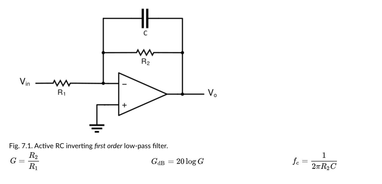
Design an inverting first order active-RC lowpass filter (Fig. 7-1) with a cutoff frequency fc of 1
Question:
Design an inverting first order active-RC lowpass filter (Fig. 7-1) with a cutoff frequency fc of 1 kHz and a gain G of 10 V/V at DC (this is the passband gain for a lowpass filter). Note, because this is an inverting filter, there will be a 180° phase shift at DC. Use resistors in the 1 kΩ - 100 kΩ range, and a capacitor in the 1-10 nF range. Apply an input of 1 V AC and obtain plots of the output voltage (on a linear scale) for an input frequency range of 1 Hz to 1 MHz (AC Sweep). Plot 10 points per decade on an exponential (decade) frequency scale. Record the gain at DC (0 Hz) and at the cutoff frequency. The ratio of these gains should be 2. The cutoff frequency is also called the 3-dB frequency because 20log2=−3dB.
Expert Answer:


Digital Signal Processing
ISBN: ?978-0133737622
3rd Edition
Authors: Jonh G. Proakis, Dimitris G.Manolakis
