

Design of a Zener Regulated DC power Supply (with Full-Wave Bridge Rectifier) Figure: Circuit Diagram of a
Fantastic news! We've Found the answer you've been seeking!
Question:
- Design of a Zener Regulated DC power Supply (with Full-Wave Bridge Rectifier)
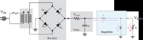
Figure: Circuit Diagram of a Zener Regulated DC Power Supply
- Design a power supply according to the following specifications.
Parameter | Value* |
Primary input voltage (rms) Vpri/ Frequency | 230 V (50 Hz) |
Maximum Ripple Factor r | 3% |
DC Capacitor Filter output voltage VDC ( at the input to regulator) | 15 V |
Maximum Load current | 100 mA |
DC output Voltage Vout | 5.1 V |
Maximum Load regulation | 2% |
- Implement the designed circuit in Multisim.
- Simulate the circuit in Multisim and verify the operation and performance
Expert Answer:
230 V 50Hz Now Voltage at point A 15v for 50HZ T C CRI chose 610625 ISV Now 7777 1s... View the full answer

Related Book For 
OM operations management
ISBN: 978-1285451374
5th edition
Authors: David Alan Collier, James R. Evans
Posted Date:
