

Figure shows a cross section of a coal loading facility on a port. Embankments (1), (2) and
Question:
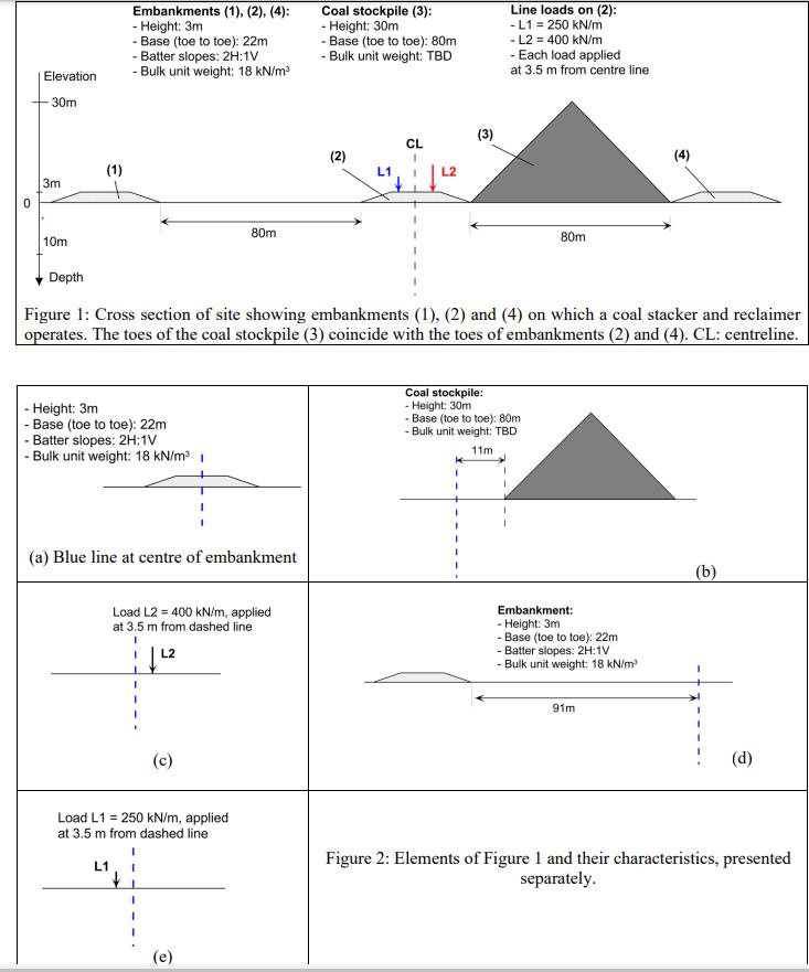
Figure shows a cross section of a coal loading facility on a port. Embankments (1), (2) and (4) support railway tracks on which a coal stacker reclaimer can travel. In Figure 1, the coal stacker reclaimer is on embankment (2) on which it imposes two line loads (L1 and L2), and the coal stockpile (3) is located in between embankments (2) and (4). It is assumed that the loading geometry of Figure 1 does not change.
The soil profile under the ground surface (at elevation = 0m) consists of 3m of loose sand overlying 17 m of silty clay on an impermeable rock stratum. The water table is.at a depth of 1m (not shown on the figure).
Some laboratory testing returned the parameters:
• Poisson's ratio for the sand and clay is 0.3
• Young's modulus of the sand is 10 MPa
• Coefficient of compressibility of clay is 0.8 MPa-1
• Void ratio of clay = 0.9, coefficient of consolidation = 12 m2 /y, coefficient of creep = 0.02
Question.
Plot the distribution of additional vertical stress and horizontal stress (in both directions) with depth (from the surface indicated by the black horizontal line in the figures, to a depth of 20m, in 0.5 m increments), at the location indicated by the blue dashed line due to the relevant surface load, for:
a. Embankment (2) (Figure 2a)
b. Coal stockpile (3) (Figure 2b) - if you have not answered Question 1, assume assume the bulk unit weight is 12 kN/m^3
c. Embankment (1) (Figure 2d)
d. Line load L2 (Figure 2c) - assume that load on embankment is equivalent to load on infinite half space
e. Line load L1 (Figure 2e) - - assume that load on embankment is equivalent to load on infinite half space.
Expert Answer:


Materials and process in manufacturing
ISBN: 978-0471656531
9th edition
Authors: E. Paul DeGarmo, J T. Black, Ronald A. Kohser
