Consider that the input shown in the below figure (here V x = ID V ). [5]
Question:
Consider that the input shown in the below figure (here Vx = ID V). [5]
![]()
![]()
![]()
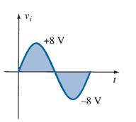
Fig. 1
Apply the knowledge gained from diode theories to construct a circuit which satisfies the following conditions and sketch the output voltage of the constructed circuit. Please explain how your circuit works and state your reasoning for your choice of circuit.
Design Criteria:
1) Only regular diodes (choose between Ge, Si, GaAs) and resistors can be used to construct the network.
2) During the positive half cycle, output VO = 0 V
3) During the negative half cycle, output VO = -(Vi – 0.3 V)
4) Diode Peak inverse voltage = Vx
Problem 2
Consider that the input shown in the below figure (here Vx = ID V ). [5]
![]()
![]()
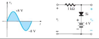
Fig. 2
Apply the knowledge gained from diode theories, determine Vo curve and explain the operating principle of the circuit shown iFig. 2.
Expert Answer: