

The focus of this exercise is an examination of basic series DC circuits with resistors. A...
Fantastic news! We've Found the answer you've been seeking!
Question:
Transcribed Image Text:
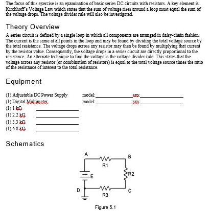
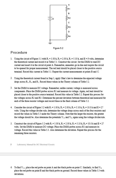
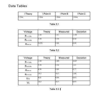
The focus of this exercise is an examination of basic series DC circuits with resistors. A key element is Kirchhoffs Voltage Law which states that the sum of voltage rises aroumd a loop must equal the sum of the voltage drops. The voltage divider rule will also be investigated. Theory Overview A series circuit is defined by a single loop in which all components are arranged in daisy-chain faskion The current is the same at all points in the loop and may be found by dividing the total voltage source by the total resistance. The voltage drops across any resistor may then be found by multiplying that curent by the resistor value. Consequently, the voltage drops in a series circuit are directly proportional to the resistance. An altemate technique to find the voltage is the voltage divider rule. This states that the voltage across any resistor (or combination of resistors) is equal to the total voltage source times the ratio of the resistance of interest to the total resistance. Equipment model: model: (1) Adjustable DC Power Supply (1) Digital Multimeter (1) 1 k0 (1)22 ka (1) 3.3 k0 (1) 6.8 kO Schematics A B R1 PR2 D. R3 Figure 5.1 A R2 R3 D R4 Figure 5.2 Procedure 1. Using the circuit of Figure 5.1 with R, = 1.00 k, R; = 2.00 k, R. = 5.10 k, and E = 9 volts, determine the theoretical current and record it in Table 5.1. Construct the circuit. Set the DMM to read DC current and insert it in the circuit at point A. Remember, ammeters go in-line and require the circuit to be opened for proper mezsurement. The red lead should be placed closer to the positive source terminal Record this current in Table 5.1. Repeat the current measurements at points B and C. 2 Using the theoretical current found in Step 1, apply Ohm's law to determine the expected voltage drops 2cross R., R, and R. Record these values in the Theory column of Table 5.2. 3. Set the DMM to measure DC voltage. Remember, unlike current, voltage is measured acroas components. Place the DMM probes across Rl and measure its voltage. Again, red lead should be placed closer to the positive source terminal. Record this value in Table 5.2 Repeat this process for the voltages across R2 and R3. Determine the percent deviation between theoretical and measured for each of the three resistor voltages and record these in the final column of Table 52 4. Consider the circuit of Figure 5.2 with R = 1.00 k, R. = 2.00 k, R, = 5.10 k, R.= 10.0 k and E =27 volts. Using the voltage divider rule, determine the voltage drops across each of the four resistors and record the values in Table 5.3 under the Theory column. Note that the larger the resistor, the greater the voltage should be. Also determine the potentials Vx. and Vn, again using the voltage divider rule. 5. Construct the circuit of Figure 5.2 with R, = 1.00 k. R. = 200 k, R. = 5.10 k, R. = 10.0 k and E = 27 volts. Set the DMM to measure DC voltage. Place the DMM probes across R1 and measure its voltage. Record this value in Table 5.3. Also determine the deviation. Repeat this process for the remaining three resistors. 3 Laboratory Manual for DC Electrical Cirouits 6. To find Va. place the red probe on point A and the black probe on point C. Similarly, to find Vn. place the red probe on point B and the black probe on ground. Record these values in Table 5.3 with deviations Data Tables I Theory I Point A Ama I Point B I Point C .Sma 1Ama 4ma Table 5.1 Voltage Theory Measured Deviation EST F1.95 R1-100k 18.38 1.39 0.30 15.076 5.08 Table 5.2 Voltage Theory Measured Deviation 1.49 0.07 Rt-1.00k 1.34 4.96 5.00 p.77 R3- th 10.2 10.3 Re-10.0k 4.81 4.84 0.62 VaC 8.5 8.7 0.97 Vs Table 5.3 | Questions 1. For the circuit of Figure 5.1, what is the expected current measurement at point D? 2. For the circuit of Figure 5.2, what are the expected current 2nd voltage measurements at point D? 3. In Figure 5.2, R, is approximately twice the size of R. and about three times the size of R. Would the voltages exhibit the same ratios? Why/why not? What about the currents through theresistors? 4. Ifa fifth resistor of 100.0 kQ was added below R, in Figure 5.2, how wvould this alter VM: and V? Show work. 5. Is KVL satisfied in Tables 5.2 and 5.3? The focus of this exercise is an examination of basic series DC circuits with resistors. A key element is Kirchhoffs Voltage Law which states that the sum of voltage rises aroumd a loop must equal the sum of the voltage drops. The voltage divider rule will also be investigated. Theory Overview A series circuit is defined by a single loop in which all components are arranged in daisy-chain faskion The current is the same at all points in the loop and may be found by dividing the total voltage source by the total resistance. The voltage drops across any resistor may then be found by multiplying that curent by the resistor value. Consequently, the voltage drops in a series circuit are directly proportional to the resistance. An altemate technique to find the voltage is the voltage divider rule. This states that the voltage across any resistor (or combination of resistors) is equal to the total voltage source times the ratio of the resistance of interest to the total resistance. Equipment model: model: (1) Adjustable DC Power Supply (1) Digital Multimeter (1) 1 k0 (1)22 ka (1) 3.3 k0 (1) 6.8 kO Schematics A B R1 PR2 D. R3 Figure 5.1 A R2 R3 D R4 Figure 5.2 Procedure 1. Using the circuit of Figure 5.1 with R, = 1.00 k, R; = 2.00 k, R. = 5.10 k, and E = 9 volts, determine the theoretical current and record it in Table 5.1. Construct the circuit. Set the DMM to read DC current and insert it in the circuit at point A. Remember, ammeters go in-line and require the circuit to be opened for proper mezsurement. The red lead should be placed closer to the positive source terminal Record this current in Table 5.1. Repeat the current measurements at points B and C. 2 Using the theoretical current found in Step 1, apply Ohm's law to determine the expected voltage drops 2cross R., R, and R. Record these values in the Theory column of Table 5.2. 3. Set the DMM to measure DC voltage. Remember, unlike current, voltage is measured acroas components. Place the DMM probes across Rl and measure its voltage. Again, red lead should be placed closer to the positive source terminal. Record this value in Table 5.2 Repeat this process for the voltages across R2 and R3. Determine the percent deviation between theoretical and measured for each of the three resistor voltages and record these in the final column of Table 52 4. Consider the circuit of Figure 5.2 with R = 1.00 k, R. = 2.00 k, R, = 5.10 k, R.= 10.0 k and E =27 volts. Using the voltage divider rule, determine the voltage drops across each of the four resistors and record the values in Table 5.3 under the Theory column. Note that the larger the resistor, the greater the voltage should be. Also determine the potentials Vx. and Vn, again using the voltage divider rule. 5. Construct the circuit of Figure 5.2 with R, = 1.00 k. R. = 200 k, R. = 5.10 k, R. = 10.0 k and E = 27 volts. Set the DMM to measure DC voltage. Place the DMM probes across R1 and measure its voltage. Record this value in Table 5.3. Also determine the deviation. Repeat this process for the remaining three resistors. 3 Laboratory Manual for DC Electrical Cirouits 6. To find Va. place the red probe on point A and the black probe on point C. Similarly, to find Vn. place the red probe on point B and the black probe on ground. Record these values in Table 5.3 with deviations Data Tables I Theory I Point A Ama I Point B I Point C .Sma 1Ama 4ma Table 5.1 Voltage Theory Measured Deviation EST F1.95 R1-100k 18.38 1.39 0.30 15.076 5.08 Table 5.2 Voltage Theory Measured Deviation 1.49 0.07 Rt-1.00k 1.34 4.96 5.00 p.77 R3- th 10.2 10.3 Re-10.0k 4.81 4.84 0.62 VaC 8.5 8.7 0.97 Vs Table 5.3 | Questions 1. For the circuit of Figure 5.1, what is the expected current measurement at point D? 2. For the circuit of Figure 5.2, what are the expected current 2nd voltage measurements at point D? 3. In Figure 5.2, R, is approximately twice the size of R. and about three times the size of R. Would the voltages exhibit the same ratios? Why/why not? What about the currents through theresistors? 4. Ifa fifth resistor of 100.0 kQ was added below R, in Figure 5.2, how wvould this alter VM: and V? Show work. 5. Is KVL satisfied in Tables 5.2 and 5.3?
Expert Answer:
Answer rating: 100% (QA)
1 Since the circuit is series combination of resistors The current is same at any point in the serie... View the full answer

Related Book For 
Fundamentals of Physics
ISBN: 978-0471758013
8th Extended edition
Authors: Jearl Walker, Halliday Resnick
Posted Date:
Students also viewed these physics questions
-
In Figure R 1 = 100? R 2 = R 3 = 50.0?, R 4 = 75.0?, and the ideal battery has emf ? = 6.00 V. (a) What is the equivalent resistance? What is i in (b) Resistance 1, (c) Resistance 2, (d) Resistance...
-
In Figure an array of n parallel resistors is connected in series to a resistor and an ideal battery. All the resistors have the same resistance. If an identical resistor were added in parallel to...
-
In Figure R 1 = R 2 = 2.0?, R 3 = 4.0?, R 4? = 3.0?, R 5 = 1.0?, and R 6 = R 7 = R 8 = 8.0?, and the ideal batteries have emf s ? 1 = 16 V and ? 2 = 8.0 V. What are the (a) Size and (b) Direction (up...
-
The comparative balance sheets for Karidis Ceramics, Inc., for December 31, 209 and 208 are presented on the next page. During 209, the company had net income of $96,000 and building and equipment...
-
List the sources of error associated with pH measurement with the glass electrode.
-
The following selected accounts and their current balances appear in the ledger of Prescott Inc. for the fiscal year ended September 30, 20Y8: Instruction 1. Prepare a multiple-step income statement....
-
A stainless-steel component is exposed to laser heating at an initial temperature of \(300 \mathrm{~K}\). After a short transient the surface reaches its melting point, and the surface recedes at a...
-
For each of the following specific audit procedures, indicate the type of audit procedure it represents: (1) Inspection of records or documents, (2) Inspection of tangible assets, (3) Observation,...
-
Given the following coding: read (x); read (y); while x #y loop if x > y then x=x-y; else y=y-x; end if; end loop; gcd := x; a) Draw the flow graph. b) Calculate the cyclomatic complexity using THREE...
-
Champ Manufacturing produces a variety of high-precision manufacturing equipment. The company is considering purchasing one component part from an outside supplier instead of making it in-house. The...
-
Prof. Saleh is driving his car from Riyadh to Madinah. He wants to take the shortest path, but his car can only drive m miles before needing to charge. Fortunately, there are AlEdresscharger charging...
-
Pioneer Inc. wants to invest $557,302 today. The expected returns in years 1, 2, and 3 are $247,615, $180,383, and $335,481, respectively. If the rate of return on investment must be at least 14%,...
-
the tuition fee for maths tuition for john is expected to be 6500 per year if he attend tuition for 4 year starting from 4 years from now how much does he have to have in her account which yields 6...
-
A 25-year-old Latin, G1P1, cisfemale presents to the office with a 6-month history of amenorrhea; reports having regular menstrual cycles every month up until about 1 year ago when her menstrual...
-
A 22-year-old college football player sustains a rough hit on the field during a practice for their biggest game of the season in 2 days. The player was knocked to the ground after a collision with...
-
a) In the conventional theory of the firm, the principal objective of a business is profit maximisation. Under the differences in consumer tastes and technology drive, price and output of a given...
-
2.A wheel of radius b rolls along the ground with constant forward speed Vo. Find the acceleration, relative to the ground, of any point on the rim. Vo 3 . P (Rotating coordinate fixed to a rolling...
-
Find the numerical value of each expression. (a) sech 0 (b) cosh -1 1
-
A dose of 8.60Ci of a radioactive isotope is injected into a patient. The isotope has a half-life of 3.0 h. Flow many of the isotope parents are injected?
-
In Figure puck 1, of mass m1 = 0.20 kg is sent sliding across a frictionless lab bench, to undergo a one-dimensional elastic collision with stationary puck 2. Puck 2 then slides off the bench and...
-
A charge of 9.0nC is uniformly distributed around a thin plastic ring lying in a yz plane with the ring center at the origin. A 6.0pC point charge is located on the x axis at x = 3.0 m. For a ring...
-
Use the \(\gamma\)-matrices in the Weyl representation to show that the Dirac equation (14.31) is equivalent to Eq. (14.25). Data from Eq. 14.31 Data from Eq. 14.25 (y"Pu-m)(p) = (iy" - m)(p) = 0
-
Prove that the boosted right-handed spinor \(\psi_{\mathrm{R}}(\boldsymbol{p})\) is related to the corresponding rest spinor by Eq. (14.21).
-
Prove the identity \((\sigma \cdot \boldsymbol{p})^{2}=\mathrm{I}^{(2)} p^{2}\), where \(\sigma=\left(\sigma_{1}, \sigma_{2}, \sigma_{3} ight)\) are the Pauli matrices, \(\boldsymbol{p}\) is the...

Study smarter with the SolutionInn App