

In this project you are going to design a traffic-light controller for the street intersection shown...
Fantastic news! We've Found the answer you've been seeking!
Question:
Transcribed Image Text:
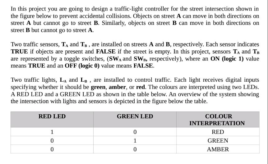
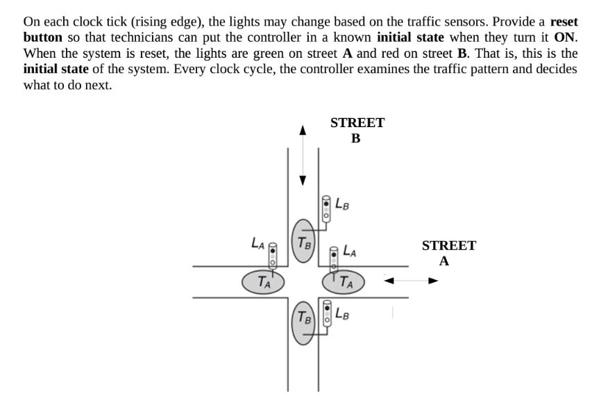
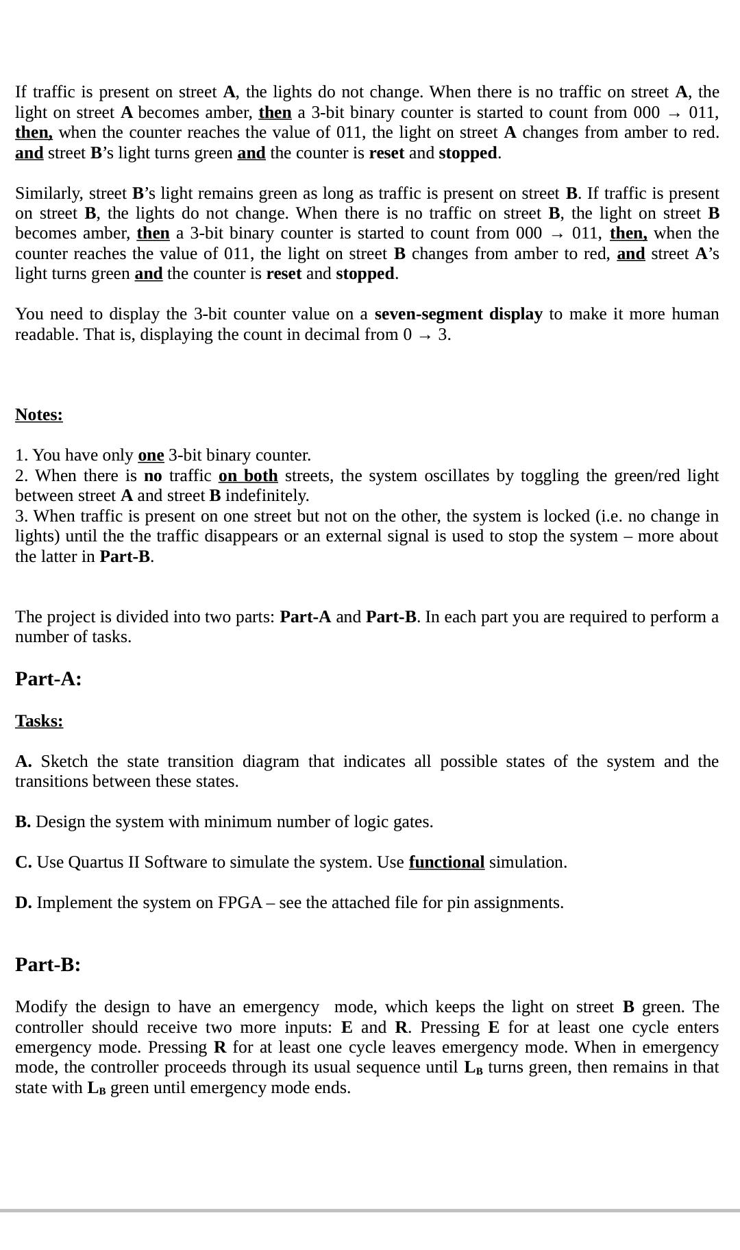
In this project you are going to design a traffic-light controller for the street intersection shown in the figure below to prevent accidental collisions. Objects on street A can move in both directions on street A but cannot go to street B. Similarly, objects on street B can move in both directions on street B but cannot go to street A. Two traffic sensors, T₁ and TB, are installed on streets A and B, respectively. Each sensor indicates TRUE if objects are present and FALSE if the street is empty. In this project, sensors T₁ and TB are represented by a toggle switches, (SWA and SWB, respectively), where an ON (logic 1) value means TRUE and an OFF (logic 0) value means FALSE. Two traffic lights, LA and LB, are installed to control traffic. Each light receives digital inputs specifying whether it should be green, amber, or red. The colours are interpreted using two LEDs. A RED LED and a GREEN LED as shown in the table below. An overview of the system showing the intersection with lights and sensors is depicted in the figure below the table. RED LED 1 0 0 GREEN LED 0 1 0 COLOUR INTERPRETATION RED GREEN AMBER On each clock tick (rising edge), the lights may change based on the traffic sensors. Provide a reset button so that technicians can put the controller in a known initial state when they turn it ON. When the system is reset, the lights are green on street A and red on street B. That is, this is the initial state of the system. Every clock cycle, the controller examines the traffic pattern and decides what to do next. LA 1.0 ΤΑ TB Тв STREET B LB LA TA LB STREET A If traffic is present on street A, the lights do not change. When there is no traffic on street A, the light on street A becomes amber, then a 3-bit binary counter is started to count from 000 011, then, when the counter reaches the value of 011, the light on street A changes from amber to red. and street B's light turns green and the counter is reset and stopped. Similarly, street B's light remains green as long as traffic is present on street B. If traffic is present on street B, the lights do not change. When there is no traffic on street B, the light on street B becomes amber, then a 3-bit binary counter is started to count from 000 → 011, then, when the counter reaches the value of 011, the light on street B changes from amber to red, and street A's light turns green and the counter is reset and stopped. You need to display the 3-bit counter value on a seven-segment display to make it more human readable. That is, displaying the count in decimal from 0 3. Notes: 1. You have only one 3-bit binary counter. 2. When there is no traffic on both streets, the system oscillates by toggling the green/red light between street A and street B indefinitely. 3. When traffic is present on one street but not on the other, the system is locked (i.e. no change in lights) until the the traffic disappears or an external signal is used to stop the system - more about the latter in Part-B. The project is divided into two parts: Part-A and Part-B. In each part you are required to perform a number of tasks. Part-A: Tasks: A. Sketch the state transition diagram that indicates all possible states of the system and the transitions between these states. B. Design the system with minimum number of logic gates. C. Use Quartus II Software to simulate the system. Use functional simulation. D. Implement the system on FPGA - see the attached file for pin assignments. Part-B: Modify the design to have an emergency mode, which keeps the light on street B green. The controller should receive two more inputs: E and R. Pressing E for at least one cycle enters emergency mode. Pressing R for at least one cycle leaves emergency mode. When in emergency mode, the controller proceeds through its usual sequence until LB turns green, then remains in that state with LB green until emergency mode ends. Tasks: A. Sketch the state transition diagram that indicates all possible states of the system and the transitions between these states. B. Design the system with minimum number of logic gates. C. Use Quartus II Software to simulate the system. Use functional simulation. In this project you are going to design a traffic-light controller for the street intersection shown in the figure below to prevent accidental collisions. Objects on street A can move in both directions on street A but cannot go to street B. Similarly, objects on street B can move in both directions on street B but cannot go to street A. Two traffic sensors, T₁ and TB, are installed on streets A and B, respectively. Each sensor indicates TRUE if objects are present and FALSE if the street is empty. In this project, sensors T₁ and TB are represented by a toggle switches, (SWA and SWB, respectively), where an ON (logic 1) value means TRUE and an OFF (logic 0) value means FALSE. Two traffic lights, LA and LB, are installed to control traffic. Each light receives digital inputs specifying whether it should be green, amber, or red. The colours are interpreted using two LEDs. A RED LED and a GREEN LED as shown in the table below. An overview of the system showing the intersection with lights and sensors is depicted in the figure below the table. RED LED 1 0 0 GREEN LED 0 1 0 COLOUR INTERPRETATION RED GREEN AMBER On each clock tick (rising edge), the lights may change based on the traffic sensors. Provide a reset button so that technicians can put the controller in a known initial state when they turn it ON. When the system is reset, the lights are green on street A and red on street B. That is, this is the initial state of the system. Every clock cycle, the controller examines the traffic pattern and decides what to do next. LA 1.0 ΤΑ TB Тв STREET B LB LA TA LB STREET A If traffic is present on street A, the lights do not change. When there is no traffic on street A, the light on street A becomes amber, then a 3-bit binary counter is started to count from 000 011, then, when the counter reaches the value of 011, the light on street A changes from amber to red. and street B's light turns green and the counter is reset and stopped. Similarly, street B's light remains green as long as traffic is present on street B. If traffic is present on street B, the lights do not change. When there is no traffic on street B, the light on street B becomes amber, then a 3-bit binary counter is started to count from 000 → 011, then, when the counter reaches the value of 011, the light on street B changes from amber to red, and street A's light turns green and the counter is reset and stopped. You need to display the 3-bit counter value on a seven-segment display to make it more human readable. That is, displaying the count in decimal from 0 3. Notes: 1. You have only one 3-bit binary counter. 2. When there is no traffic on both streets, the system oscillates by toggling the green/red light between street A and street B indefinitely. 3. When traffic is present on one street but not on the other, the system is locked (i.e. no change in lights) until the the traffic disappears or an external signal is used to stop the system - more about the latter in Part-B. The project is divided into two parts: Part-A and Part-B. In each part you are required to perform a number of tasks. Part-A: Tasks: A. Sketch the state transition diagram that indicates all possible states of the system and the transitions between these states. B. Design the system with minimum number of logic gates. C. Use Quartus II Software to simulate the system. Use functional simulation. D. Implement the system on FPGA - see the attached file for pin assignments. Part-B: Modify the design to have an emergency mode, which keeps the light on street B green. The controller should receive two more inputs: E and R. Pressing E for at least one cycle enters emergency mode. Pressing R for at least one cycle leaves emergency mode. When in emergency mode, the controller proceeds through its usual sequence until LB turns green, then remains in that state with LB green until emergency mode ends. Tasks: A. Sketch the state transition diagram that indicates all possible states of the system and the transitions between these states. B. Design the system with minimum number of logic gates. C. Use Quartus II Software to simulate the system. Use functional simulation.
Expert Answer:
Answer rating: 100% (QA)
A State Transition Diagram The state transition diagram for the traffic light controller system can ... View the full answer

Related Book For 

Principles of Information Systems
ISBN: 978-1133629665
11th edition
Authors: Ralph Stair, George Reynolds
Posted Date:
Students also viewed these accounting questions
-
An ideal monoatomic gas is confined in a horizontal cylinder by a spring loaded piston (as shown in the figure). Initially the gas is at temperature T, pressure P and volume V, and the spring is in...
-
Stockholders' equity of Ernst Company consists of 82,000 shares of $5 par value, 10% cumulative preferred stock and 290,000 shares of $1 par value common stock. Both classes of stock have been...
-
In August 2014, Jim acquired a 99-year lease on a flat for 170,000. In August 2020, he assigned the lease to Shirley for 212,000. The flat was never Jim's residence. Compute the chargeable gain.
-
A semicircle of radius is in the first and second quadrants, with the center of curvature at the origin. Positive charge + Q is distributed around the left half of the semicircle (0 to 90 degrees)...
-
Estimated expenditures and cash flows for the two projects are shown below. Year Project A Project B 0 (350,000) (3,500,000) 1 150,000 150,000 2 150,000 150,000 3 100,000 750,000 4 75,000 1,500,000 5...
-
How does an EIA statement add value for internal management?
-
On June 1, 2011, MacDougall Corporation approached Silverman Corporation about purchasing a parcel of undeveloped land. Silverman was asking $240,000 for the land and MacDougall saw that there was...
-
Tommy arranged a P10,000,000 revolving credit agreement with a group of banks. The company paid an annual commitment fee of 0.5% of the unused balance of the loan commitment. On the used portion of...
-
Complete General entries for following question: Gordon Corporation is a company that specializes in the design of custom hardware and software solutions for manufacturing companies. The company is...
-
The density of polonium metal is 9.2 g/cm. If the extended lattice of polonium exhibits a simple cubic unit cell, estimate the atomic radius of polonium. Radius pm
-
Grand Corporation reported pretax book income of $600,000. Tax depreciation exceeded book depreciation by $400,000. In addition, the company received $300,000 of tax-exempt municipal bond interest....
-
Crane Company is considering a capital investment of $369,600 in additional productive facilities. The new machinery is expected to have useful life of 6 years with no salvage value. Depreciation is...
-
You were elected to the Parliament of Canada and because of your technical expertise you were appointed on the parliament technical review committee that recommends new legislation related to...
-
Wang Supply prepares monthly financial statements. Listed below are some selected accounts and their balances at June 30. Adjustments generally are done monthly, but no adjustments have been made for...
-
Carla Vista Inc. makes two types of handbags: standard and custom. The controller has decided to use a plant-wide overhead rate based on direct labour costs. The president has heard of activity-based...
-
Add new computer hardware option exists in a. control panel b. task bar c. main menu d. status bar
-
Which should drive action planning more, strengths or weaknesses? That is, is it more important to build on your strengths or to reduce your weaknesses? Explain.
-
What are the stages of problem solving?
-
What is the difference between freeware and open-source software?
-
What types of services will be provided over Altitude Onlines network?
-
What is a bivariate distribution function?
-
True or False. The expected value of \(x\), in terms of its probability density function, \(p(x)\), is given by \(\int_{-\infty}^{\infty} x p(x) d x\).
-
Find the temporal mean value and the mean square value of the function \(x(t)=x_{0} \sin (\pi t / 2)\).

Study smarter with the SolutionInn App