

Never connect the Positive (+) lead of a power supply to the ground. Connect the negative lead
Question:
Never connect the Positive (+) lead of a power supply to the ground. Connect the negative lead of the power supply to the circuit FIRST. Then, connect the positive lead.
Parts:
Breadboard
DC Power Supply
Hand-Held DMM
Test leads
1k? resistor
2.2k? resistor
5.6k? resistor

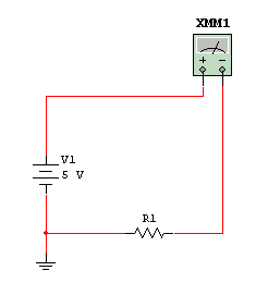
1. Construct the circuit shown above by:
A. Connect the +5 V and ground connections from the DC power supply to the +Voltage (+/Red) and ground stripes (-/Blue) on the breadboard.
B. Obtain a 1k? resistor and place it into the breadboard so that one lead is connected to the negative terminal strip.
C. Connect the negative or common hand-held DMM terminal to the non-connected lead of the 1k? resistor.
D. Place a wire into the ‘+’ power strip on the breadboard and connect this wire to the positive input terminal of your hand-held DMM.
E. Have the professor verify these connections before applying power.
2. Use Ohm’s Law and calculate and record the Current (I) through the 1k? in Table 1.
3. Set the hand-held DMM to measure current at the appropriate scale based on the calculation above. Apply power to the circuit and measure and record the current (I) through the 1k? in Table 1.
4. Turn off the power supply and replace the 1k? resistor with the 2.2k?. Use Ohm’s Law and calculate and record the current (I) through the 2.2k? in Table 1.
5. Turn on the power supply and measure and record the current (I) through the 2.2k? in Table 1.
6. Did the measured values agree with the calculated results (YES/NO)? If not, determine the problem and repeat the measurement.
7. Turn off the power supply and replace the 2.2k? resistor with the 5.6k?. Calculate the current and record it in Table 1. Measure the current and record it in Table 1.
| Component | Calculated Current | Hand-Held DMM Measured Current | ELVIS DMM Measured Current (if applicable) | |
| 1 | 1k? | |||
| 2 | 2.2k? | |||
| 3 | 5.6k? | |||
| 4 | Open Circuit |
Table 1
8. If you are using an ELVIS unit, repeat Steps 3 through 5 using the ELVIS DMM and record the results in Table 1. If you are NOT using an ELVIS unit, skip to Step 10.
9. Should the ELVIS measurements agree with the hand-held DMM measurements? (YES/NO) Were the measurements in agreement? (YES/NO) If not, determine the problem and repeat the measurement.
10. In a few sentences, explain in your own words what you have learned about current through a series circuit.
Part 2
Parts:
Breadboard
DC Power Supply
Hand-Held DMM
Test leads
1k? resistor
3.3k? resistor
1. Using Ohm’s Law, calculate the total current in the circuit above. Then, determine the voltage drop across R1. Record the results in Table 1.
2. Connect the breadboard to the +5 V supply by connecting the ground (-/Blue) and positive stripe (+/Red) of the breadboard to ground and +5 V connections on the DC power supply.
3. Verify the +5 V voltage by using the hand-held DMM.
A. Connect the hand-held DMM leads as shown below. Have the professor verify the connections.
B. Set the hand-held DMM to measure voltage. Choose the appropriate scale.
C. Turn on DC power supply.
D. What voltage did the hand-held DMM read? __________. Is this correct (YES/NO)? If not, correct the problem and make the measurement again.
4. Obtain a 1k? resistor and place it into the breadboard.
A. Jumper the positive terminal strip to one end of the 1k? resistor.
B. Jumper the other end of the 1k? resistor to the negative terminal strip.
C. Connect the hand-held DMM voltmeter across the 1k? resistor as shown below.
D. Examine the circuit to check all connections.
5. Using the same technique that you used above, measure the voltage across the 1k? resistor and record its value in Table 1 below.
6. Turn off the power supply and replace the 1k? resistor with the 3.3k?.
7. Turn on the power supply and measure and record the voltage (V) across the 3.3k? resistor, and record its value in Table 1 below.
| Component | Calculated Voltage | Hand-Held DMM Measured Voltage | ELVIS DMM Measured Voltage (if applicable) | |
| 1 | 1kW | |||
| 2 | 3.3kW |
Table 1
8. If you are using an ELVIS environment, use the same procedure as above and measure the voltage across the 1kW and 3.3kW resistors with the ELVIS DMM. Record the measurements in Table 1. If you are NOT using an ELVIS unit, skip to Step 10.
9. Should the ELVIS DMM measurements agree with the hand-held DMM measurements? (YES/NO) Were the measurements in agreement? (YES/NO) If not, determine the problem and repeat the measurement.
10. In one or two paragraphs, explain in your own words how to measure voltage in a series circuit.
Expert Answer:
Certainly I can guide you through the steps and provide an example of how to approach the calculations Heres a simplified version Part 2 Parts Breadbo... View the full answer


Managing Controlling and Improving Quality
ISBN: 978-0471697916
1st edition
Authors: Douglas C. Montgomery, Cheryl L. Jennings, Michele E. Pfund
