

You have been asked to design a shunt regulator with the following specifications: Input voltage: between
No answer yet for this question.
Ask a Tutor
Question:
● Input voltage: between 10 and 15V
● Output voltage: nominally 5.6V
● Load current: nominally 10mA
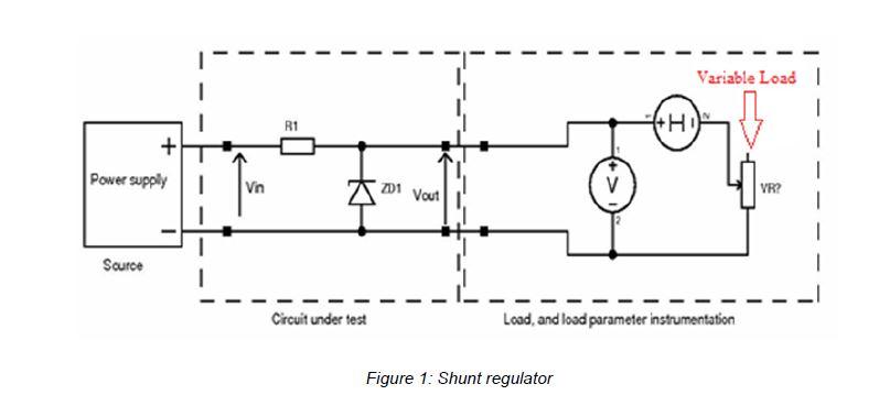
The experimental set-up you will need is shown in (Figure 1). Each workstation will have sufficient power supplies and meters along with printed circuit boards. The variable load you will need is a variable potentiometer. A range of resistors are in the racks on the wall and you need to request them from the supervisor with the duly filled lab requisition form. PLEASE ENSURE YOU RETURN COMPONENTS TO SUPERVISOR WITH THE DULY COMPLETED LAB REQUISITION FORM
Ensure all experimental notes are written up in your lab books: you may need them in submitting the
coursework.
i. Prepare the components for a simple zener shunt regulator to meet the above specification - record
the values in your lab books.
ii. Complete the circuit of shunt regulator on the provided PCB. The meters, zener diode and the resistors will have to be plugged. BEFORE APPLYING ANY POWER quickly have your circuit
Set the variable load to its highest value, then:
iii. With the power supply set to the bottom of the specified range of input voltages, plot regulator load voltage to a base of load current in your lab books (you can use a spreadsheet program/MATLAB to do the plotting when compiling the report - but remember that all curves should be smooth). The
load current should be increased by reducing the load resistance via the variable load resistor. Take voltage readings every 1mA of load current until the maximum current is passed. Identify:
a. the maximum load voltage from the regulator
b. the maximum load current from the regulator
iv. Repeat part (iii) with the power supply set to the top of the specified range, until the maximum current is passed in 2 mA steps
v. With reference to the experimental data you obtained, answer the following questions in your lab books. You will need this information later to help you effectively prepare the first coursework
component.
a. Is the maximum load voltage constant with input voltage?
b. Is the maximum load current constant with input voltage?
c. Does the output characteristic (what you plotted in (iii) and (iv)) differ generally with respect to the input voltage? If so, how?
d. A portion of the output characteristic will show a load voltage that is constant with load current. In the constant voltage portion, how close is the constant voltage to the zener
voltage? Is this what you expect? If not, why not?
e. At what point does the load voltage significantly deviate from the constant voltage part of the curve? At this point, calculate the zener current (Hint: you know the input voltage,
the resistor value, the output voltage, and the output current).
9
vi. Measure the efficiency curve of the regulator for both input voltages specified.
(Hint: you will need to measure the input current as well: you may need another meter). What efficiency figure do you get?
What is the most efficient operating point of the regulator?
vii. Simulate the regulator in Multisim.Figure 1: Shunt regulator
Expert Answer:

Related Book For 

Fundamentals Of Corporate Finance
ISBN: 9780135811603
5th Edition
Authors: Jonathan Berk, Peter DeMarzo, Jarrad Harford
Posted Date:
