

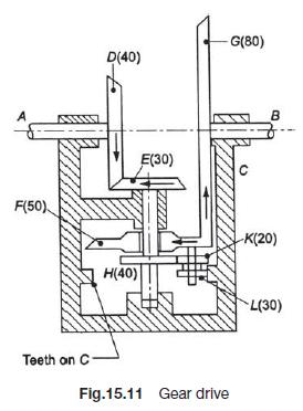
In the gear drive shown in Fig.15.11, the driving shaft A rotates at 300 rpm in the
Fantastic news! We've Found the answer you've been seeking!
Question:
In the gear drive shown in Fig.15.11, the driving shaft A rotates at 300 rpm in the clockwise direction,
when seen from the left hand side. The shaft B is the driven shaft. The casing C is held stationary. The
wheels E and H are keyed to the central vertical spindle and wheel F can rotate freely on this spindle.
The wheels K and L are rigidly fixed to each other and rotate together freely on a pin fitted on the
underside of F. The wheel L meshes with internal teeth on the casing C. The number of teeth on the
different gears are indicated within brackets.
Determine the number of teeth on gear C and the speed and direction of rotation of shaft B.
Expert Answer:
From the figure we can see that Gear E 24 teeth is fixed to the driving shaft A which rotates at 300 rpm clockwise Gear F 30 teeth is free to rotate o... View the full answer

Related Book For 

Fundamentals of Thermal-Fluid Sciences
ISBN: 978-0078027680
5th edition
Authors: Yunus A. Cengel, Robert H. Turner, John M. Cimbala
Posted Date:
