

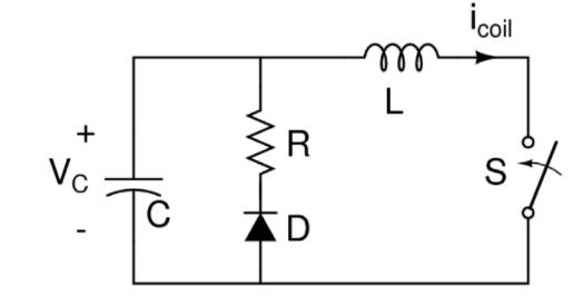
Shown in Figure 0.1 is a diagram of a circuit used to generate a large pulsed magnetic
Fantastic news! We've Found the answer you've been seeking!
Question:
Shown in Figure 0.1 is a diagram of a circuit used to generate a large pulsed magnetic field. The capacitor is pre-charged to a voltage Vx, which can be between 0 and 1000 V. At time t=0, the switch S is closed to trigger the magnetic pulse. The value of R is 80 mΩ, C is 180 μF, and L is 12 μH. Theswitch S and diode D are ideal.
Calculate the following:
1. The time response of the coil current (icoil) after the switch S is closed, as a function of the pre-charge voltage Vx.
2. The peak coil current for Vx = 1000 V.
3. The time t1 at which diode D turns on.
4. The energy dissipated in the resistor R for Vx = 1000 V.
Expert Answer:

Related Book For 
Essential University Physics
ISBN: 978-0321976420
3rd Edition Volume 2
Authors: Richard Wolfsonby, Richard Wolfson
Posted Date:
