

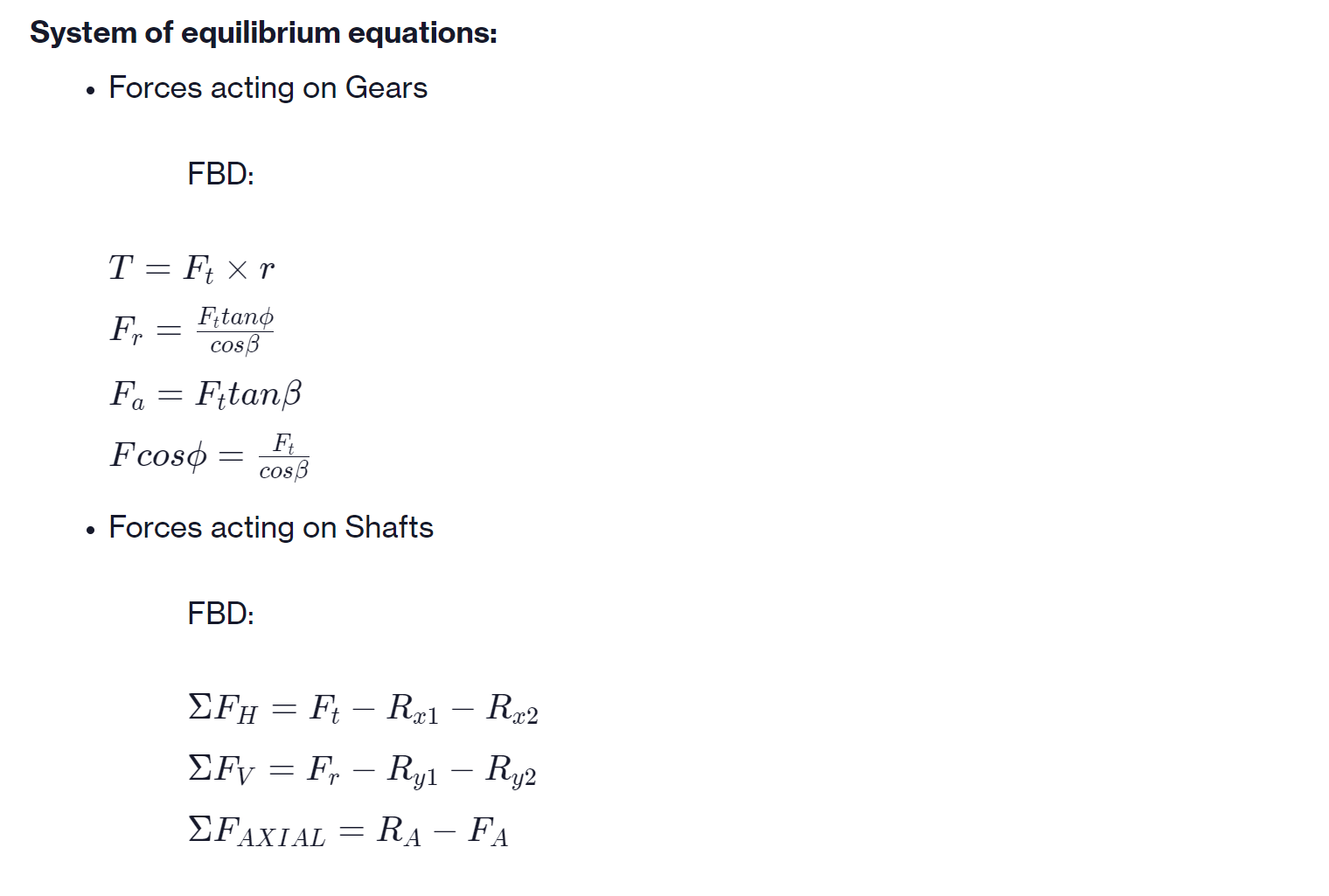
System of equilibrium equations: Forces acting on Gears T = Ft xr Fitano cos Fa= Fttan...
Fantastic news! We've Found the answer you've been seeking!
Question:
Transcribed Image Text:
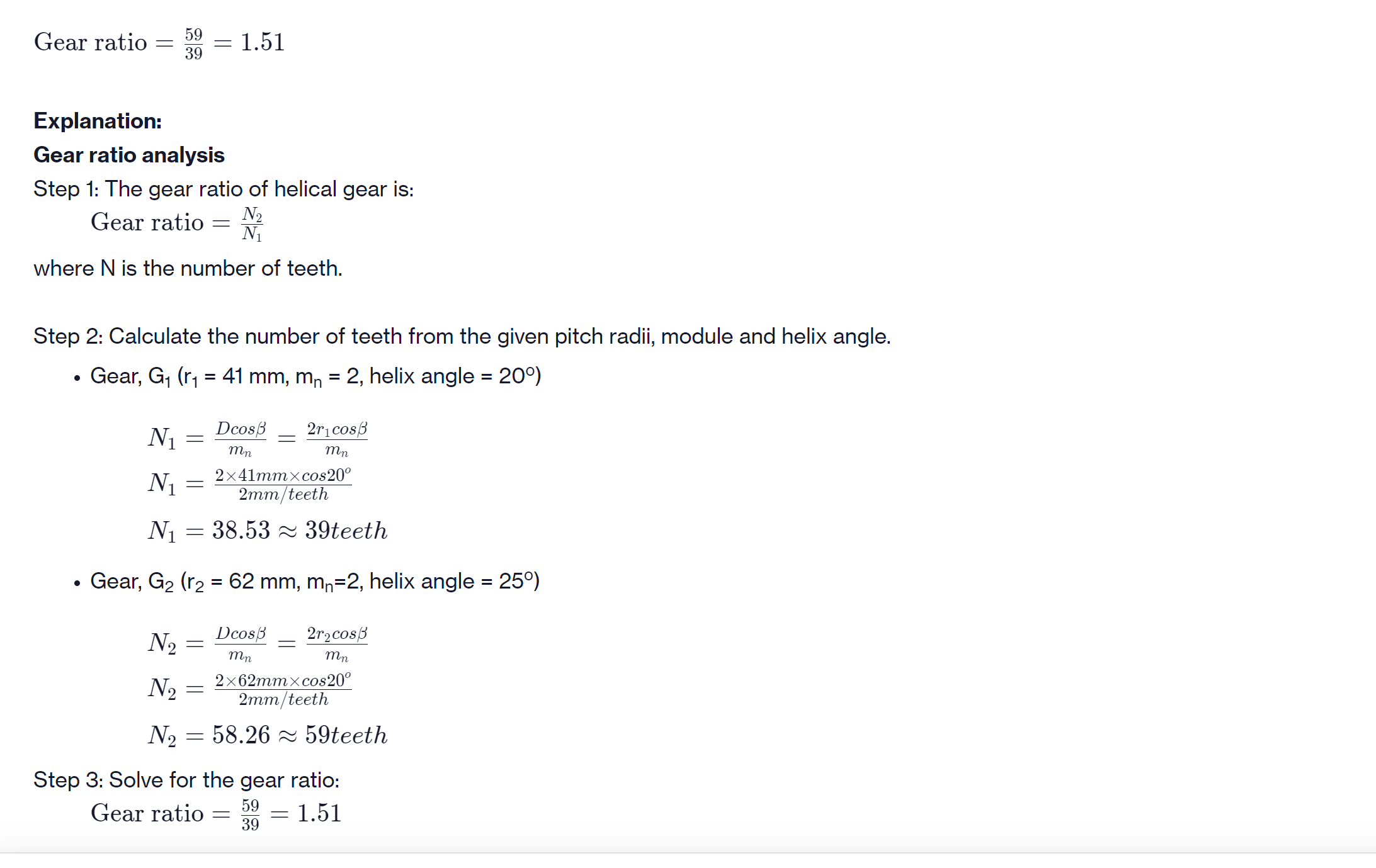
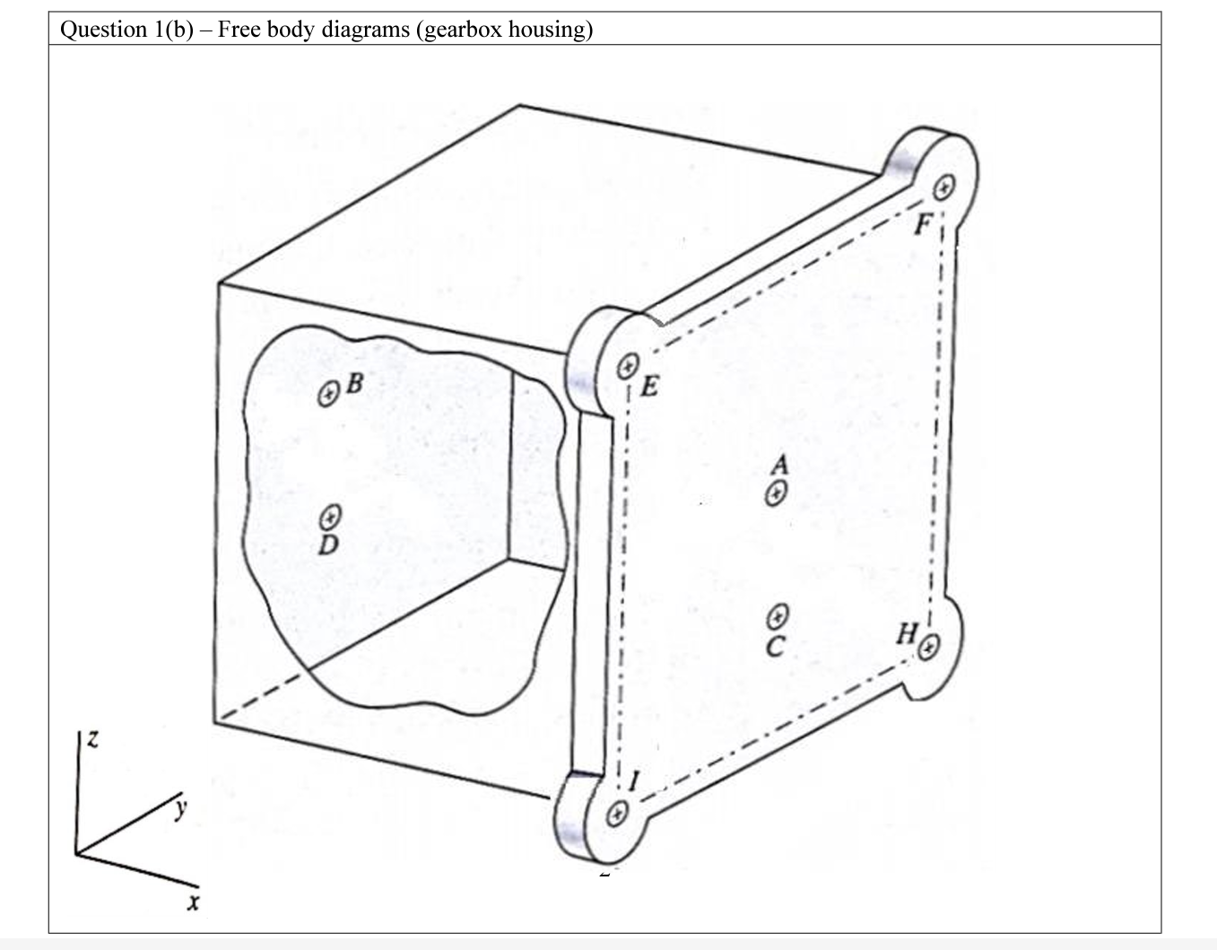
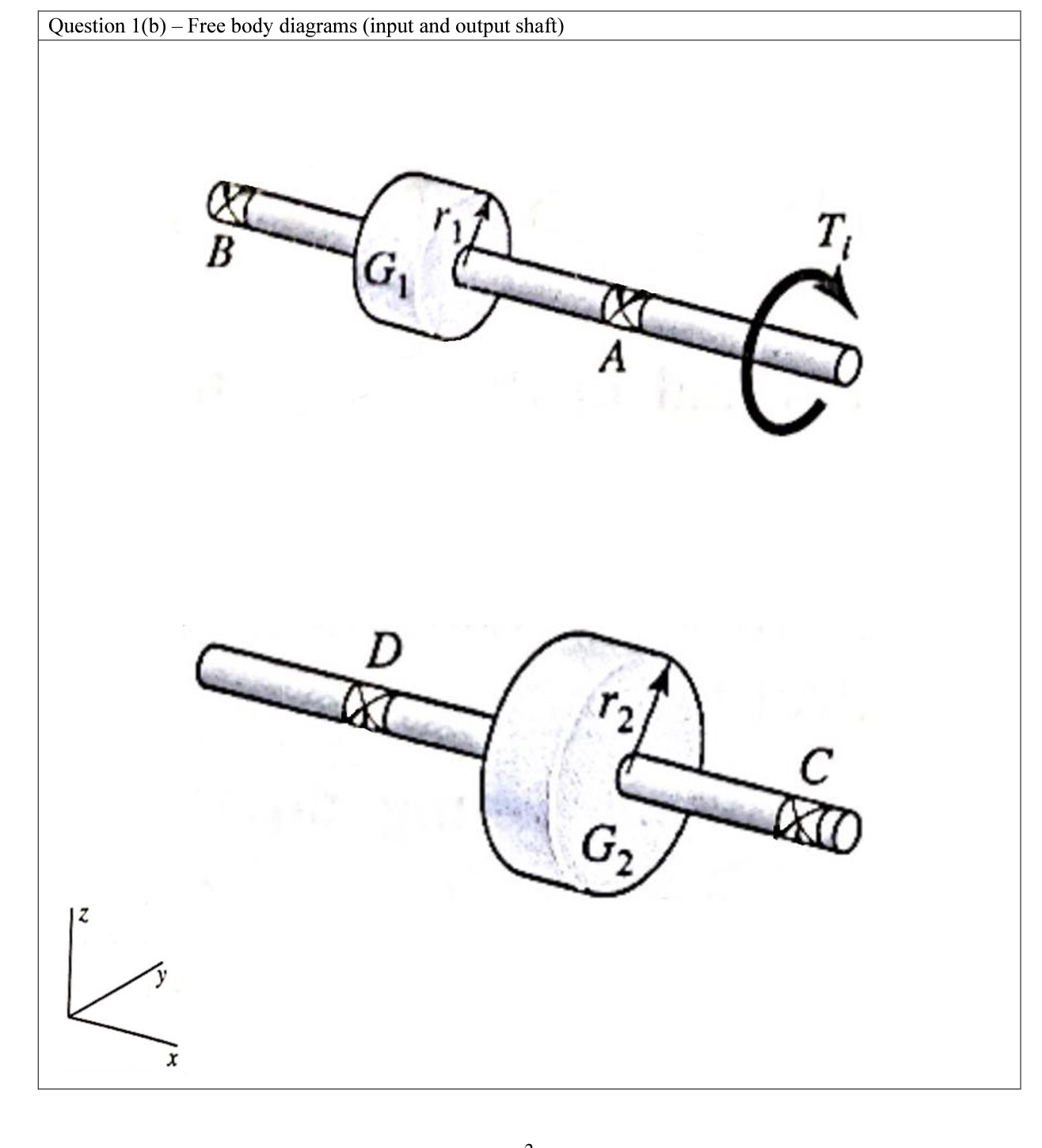
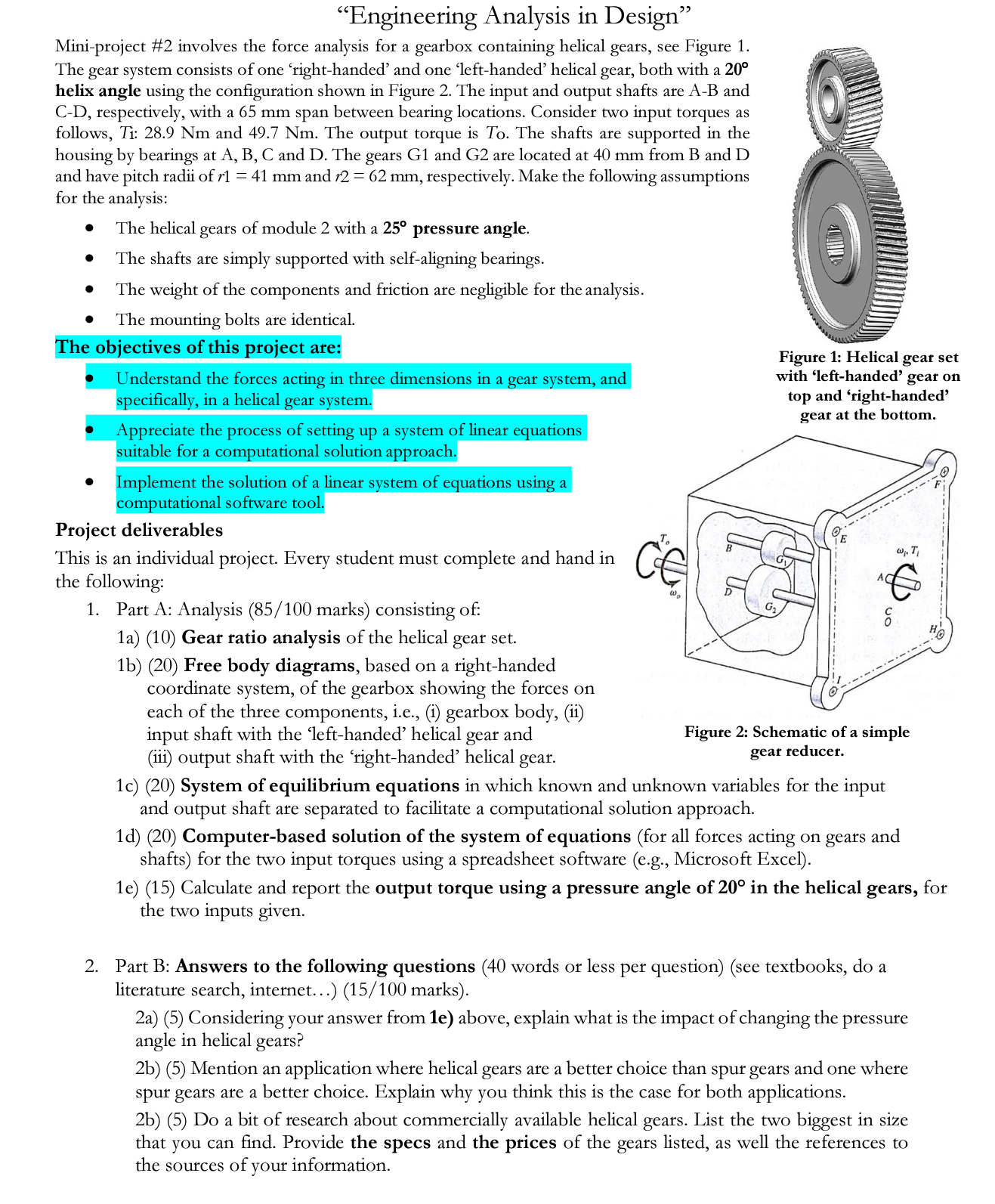
System of equilibrium equations: Forces acting on Gears T = Ft xr Fitano cos Fa= Fttan Fcoso Fr FBD: = - Ft cos Forces acting on Shafts FBD: FH = Ft R1 - Rx2 Fy Fr Ry1 - Ry2 = FAXIAL = RA - FA FBD: 8 T = Ft xr Fitano Fr cos Fa Fitan Fcoso Forces acting on Shafts FBD: = F cos RA (AXIAL REACTION) FH = Ft R1 - Rx2 Fy Fr Ryl - Ry2 FAXIAL = RA - FA OXI Ft Rx Ry (BEARING REACTION) B Fa Frost Fa Fcos Ry Rx Fa Foos Gear ratio = Explanation: Gear ratio analysis Step 1: The gear ratio of helical gear is: Gear ratio N N where N is the number of teeth. 59 39 N Step 2: Calculate the number of teeth from the given pitch radii, module and helix angle. Gear, G ( = 41 mm, m = 2, helix angle = 20) = N N = - = : 1.51 = Dcos mn N N = 38.53 39teeth = mn 2x41mmxcos 20 2mm/teeth Gear, G (r = 62 mm, m=2, helix angle = 25) Dcos mn 2r1 cos - - 2x62mmxcos20 2mm/teeth N = 58.26 59teeth 2rcos mn Step 3: Solve for the gear ratio: 59 Gear ratio 1.51 39 = Question 1(b) - Free body diagrams (gearbox housing) E HO Question 1(b) - Free body diagrams (input and output shaft) X B G D (X A G T IXO "Engineering Analysis in Design" Mini-project #2 involves the force analysis for a gearbox containing helical gears, see Figure 1. The gear system consists of one right-handed' and one left-handed' helical gear, both with a 20 helix angle using the configuration shown in Figure 2. The input and output shafts are A-B and C-D, respectively, with a 65 mm span between bearing locations. Consider two input torques as follows, Ti: 28.9 Nm and 49.7 Nm. The output torque is To. The shafts are supported in the housing by bearings at A, B, C and D. The gears G1 and G2 are located at 40 mm from B and D and have pitch radii of r1 = 41 mm and r2 = 62 mm, respectively. Make the following assumptions for the analysis: The helical gears of module 2 with a 25 pressure angle. The shafts are simply supported with self-aligning bearings. The weight of the components and friction are negligible for the analysis. The mounting bolts are identical. The objectives of this project are: Understand the forces acting in three dimensions in a gear system, and specifically, in a helical gear system. Appreciate the process of setting up a system of linear equations suitable for a computational solution approach. Implement the solution of a linear system of equations using a computational software tool. Project deliverables This is an individual project. Every student must complete and hand in the following: 1. Part A: Analysis (85/100 marks) consisting of: 1a) (10) Gear ratio analysis of the helical gear set. 1b) (20) Free body diagrams, based on a right-handed coordinate system, of the gearbox showing the forces on each of the three components, i.e., (i) gearbox body, (ii) input shaft with the 'left-handed' helical gear and (iii) output shaft with the 'right-handed' helical gear. CE @ Figure 1: Helical gear set with 'left-handed' gear on top and 'right-handed gear at the bottom. o 1c) (20) System of equilibrium equations in which known and unknown variables for the input and output shaft are separated to facilitate a computational solution approach. w. T Figure 2: Schematic of a simple gear reducer. 1d) (20) Computer-based solution of the system of equations (for all forces acting on gears and shafts) for the two input torques using a spreadsheet software (e.g., Microsoft Excel). 2. Part B: Answers to the following questions (40 words or less per question) (see textbooks, do a literature search, internet...) (15/100 marks). 1e) (15) Calculate and report the output torque using a pressure angle of 20 in the helical gears, for the two inputs given. 2a) (5) Considering your answer from 1e) above, explain what is the impact of changing the pressure angle in helical gears? 110 2b) (5) Mention an application where helical gears are a better choice than spur gears and one where spur gears are a better choice. Explain why you think this is the case for both applications. H! 2b) (5) Do a bit of research about commercially available helical gears. List the two biggest in size that you can find. Provide the specs and the prices of the gears listed, as well the references to the sources of your information. System of equilibrium equations: Forces acting on Gears T = Ft xr Fitano cos Fa= Fttan Fcoso Fr FBD: = - Ft cos Forces acting on Shafts FBD: FH = Ft R1 - Rx2 Fy Fr Ry1 - Ry2 = FAXIAL = RA - FA FBD: 8 T = Ft xr Fitano Fr cos Fa Fitan Fcoso Forces acting on Shafts FBD: = F cos RA (AXIAL REACTION) FH = Ft R1 - Rx2 Fy Fr Ryl - Ry2 FAXIAL = RA - FA OXI Ft Rx Ry (BEARING REACTION) B Fa Frost Fa Fcos Ry Rx Fa Foos Gear ratio = Explanation: Gear ratio analysis Step 1: The gear ratio of helical gear is: Gear ratio N N where N is the number of teeth. 59 39 N Step 2: Calculate the number of teeth from the given pitch radii, module and helix angle. Gear, G ( = 41 mm, m = 2, helix angle = 20) = N N = - = : 1.51 = Dcos mn N N = 38.53 39teeth = mn 2x41mmxcos 20 2mm/teeth Gear, G (r = 62 mm, m=2, helix angle = 25) Dcos mn 2r1 cos - - 2x62mmxcos20 2mm/teeth N = 58.26 59teeth 2rcos mn Step 3: Solve for the gear ratio: 59 Gear ratio 1.51 39 = Question 1(b) - Free body diagrams (gearbox housing) E HO Question 1(b) - Free body diagrams (input and output shaft) X B G D (X A G T IXO "Engineering Analysis in Design" Mini-project #2 involves the force analysis for a gearbox containing helical gears, see Figure 1. The gear system consists of one right-handed' and one left-handed' helical gear, both with a 20 helix angle using the configuration shown in Figure 2. The input and output shafts are A-B and C-D, respectively, with a 65 mm span between bearing locations. Consider two input torques as follows, Ti: 28.9 Nm and 49.7 Nm. The output torque is To. The shafts are supported in the housing by bearings at A, B, C and D. The gears G1 and G2 are located at 40 mm from B and D and have pitch radii of r1 = 41 mm and r2 = 62 mm, respectively. Make the following assumptions for the analysis: The helical gears of module 2 with a 25 pressure angle. The shafts are simply supported with self-aligning bearings. The weight of the components and friction are negligible for the analysis. The mounting bolts are identical. The objectives of this project are: Understand the forces acting in three dimensions in a gear system, and specifically, in a helical gear system. Appreciate the process of setting up a system of linear equations suitable for a computational solution approach. Implement the solution of a linear system of equations using a computational software tool. Project deliverables This is an individual project. Every student must complete and hand in the following: 1. Part A: Analysis (85/100 marks) consisting of: 1a) (10) Gear ratio analysis of the helical gear set. 1b) (20) Free body diagrams, based on a right-handed coordinate system, of the gearbox showing the forces on each of the three components, i.e., (i) gearbox body, (ii) input shaft with the 'left-handed' helical gear and (iii) output shaft with the 'right-handed' helical gear. CE @ Figure 1: Helical gear set with 'left-handed' gear on top and 'right-handed gear at the bottom. o 1c) (20) System of equilibrium equations in which known and unknown variables for the input and output shaft are separated to facilitate a computational solution approach. w. T Figure 2: Schematic of a simple gear reducer. 1d) (20) Computer-based solution of the system of equations (for all forces acting on gears and shafts) for the two input torques using a spreadsheet software (e.g., Microsoft Excel). 2. Part B: Answers to the following questions (40 words or less per question) (see textbooks, do a literature search, internet...) (15/100 marks). 1e) (15) Calculate and report the output torque using a pressure angle of 20 in the helical gears, for the two inputs given. 2a) (5) Considering your answer from 1e) above, explain what is the impact of changing the pressure angle in helical gears? 110 2b) (5) Mention an application where helical gears are a better choice than spur gears and one where spur gears are a better choice. Explain why you think this is the case for both applications. H! 2b) (5) Do a bit of research about commercially available helical gears. List the two biggest in size that you can find. Provide the specs and the prices of the gears listed, as well the references to the sources of your information.
Expert Answer:

Related Book For 
Vector Mechanics for Engineers Statics and Dynamics
ISBN: 978-0073212227
8th Edition
Authors: Ferdinand Beer, E. Russell Johnston, Jr., Elliot Eisenberg, William Clausen, David Mazurek, Phillip Cornwell
Posted Date:
Students also viewed these mechanical engineering questions
-
4) Solve the following problems: 9 (b) 1. Apply the DFS based topological sort algorithm to the graph on the left; Your DFS traversal will start with vertext a. Write down the nodes visited during a...
-
Researcher A observes a sample of 10 subjects four times and decides to retain the null hypothesis. Researcher B also observes a sample of 10 subjects four times and obtains the same group means, but...
-
Use a pie chart to display the data, which represent the number of mens New York City Marathon winners from each country through 2016. Organize the data using the indicated type of graph. Describe...
-
Millions of high school graduates decide annually to enroll in a college or university. Many factors can influence a students choice of where to enroll. List the five steps of the decision-making...
-
The following information was taken from the accounting records of Mitchell Company for last year: Management wants to organize these data into a better format so that financial statements can be...
-
What was the purpose for here I stand the BIOGRAPHY OF Martin Luther. Why is it important to establish the meaning of talent and talent management in a particular organizational setting? How does the...
-
You currently own a technology stock that has an expected return of 14.9% and its beta is 1.44. The expected return on the overall stock market is 11.60%. The inflation rate is currently 2.00%. Using...
-
The average return for Firm A is calculated as 0.05 (5%) with a standard deviation of 0.03. The average return for Firm B is calculated as 0.15 (15%) with a standard deviation of 0.06. The covariance...
-
Suppose your expenses for this term are as follows: tuition: $12,000 , room and board: $6,500 , books and other educational supplies: $1,500 . Further, during the term, you can only work part-time...
-
Evaluate each limit using algebraic methods, if the limit exists. lim x-0 x +55 - x X 1 Tim - - ( 2 + x - 2)
-
In 2023 , Amalgamated Industries' net fixed assets decreased from $380,000 to $260,000 . depreciation expense for the period was $90,000 . What was Net Capital Spending for 2023?
-
The frame shown in Figure Q2 has rigid floors and can be considered as a "shear frame". The masses are lumped onto the floor slabs as shown in the Figure. Determine (i) the structure stiffness matrix...
-
The following figure shows a port address decoder interfaced to an 8086 CPU, (According to text book) 07 Data Bus A7 DO Dout AS LE E1 E2 01 A3 02 C (LSB) 8 74LS138 A A2 04 OS 40 07 Din Dou 06 Osta...
-
Establish identity. cos( + k) = (-1)k cos , k any integer
-
Determine the vertical force P which must be applied at G so that the linkage is in equilibrium for the position shown. 1.2 in. 3.6 in.- 20 lb 1,6 in. 15 lb-ft 1.6 in.
-
A temporary dam is constructed in a 1.5-m-wide freshwater channel by nailing two boards to pilings located at the sides of the channel and propping a third board AB against the pilings and the floor...
-
A particle moves in a straight line with a constant acceleration of ??2 m/s2 for 6 s, zero acceleration for the next 4 s, and a constant acceleration of +2 m/s2 for the next 4 s. Knowing that the...
-
The swinging spring is an example of a two degree-of-freedom system with a cubic nonlinearity. Indicate whether the statement presented is true or false. If true, state why. If false, rewrite the...
-
The period of free vibrations of a nonlinear system depends upon initial conditions. Indicate whether the statement presented is true or false. If true, state why. If false, rewrite the statement to...
-
A mass attached to a linear spring sliding on a surface with Coulomb damping is an example of a nonlinear system. Indicate whether the statement presented is true or false. If true, state why. If...

Study smarter with the SolutionInn App