

The compound shaft shown in Figure P6.42/43 consists of a solid aluminum segment (1) and a hollow
Fantastic news! We've Found the answer you've been seeking!
Question:
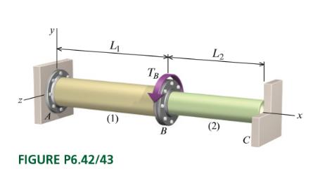
The compound shaft shown in Figure P6.42/43 consists of a solid aluminum segment (1) and a hollow brass segment (2) that are connected at flange B and securely attached to rigid supports at A and C. Aluminum segment (1) has a diameter of 0.875 in., a length L45 in., a shear modulus of 3,800 ksi, and an allowable shear stress of 6 ksi. Brass segment (2) has an outside diameter of 0.68 in a wall thickness of 0.09 in., a length L2-30 in., a shear modulus of 6,400 ksi, and an allowable shear stress of 8 ksi. Determine
(a) the allowable torque TB that can be applied to the compound shaft at flange B.
(b) the magnitudes of the internal torques in segments (1) and (2)
(c) the rotation angle of flange B that is produced by the allowable torque TB.
Expert Answer:

Related Book For 
Posted Date:
