

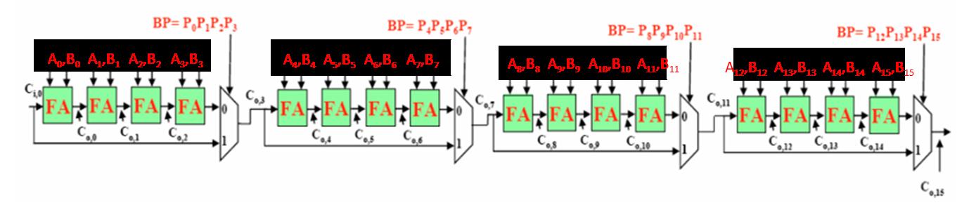
The figure below shows a 16-bit carry-bypass adder. The inputs are denoted as (A 15 A 14
Fantastic news! We've Found the answer you've been seeking!
Question:
The figure below shows a 16-bit carry-bypass adder. The inputs are denoted as (A15A14…A0) and (B15B14…B0), where A15 and B15 are the MSBs. Pi and Gi follow the definitions in the lecture (i.e., Pi=Ai xor Bi, Gi=Ai & Bi). Outputs Si are omitted for simplicity. Please note that independent calculations can be performed concurrently in hardware (e.g., all Pi’s and Gi’s can be calculated simultaneously).
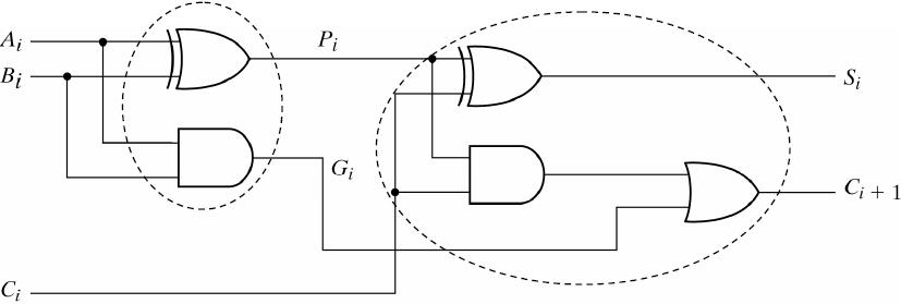
The following figure shows the detail inside each full adder based on P and G.
 |
Expert Answer:
Inputs The adder takes two 16bit binary numbers A and B as inputs Each bit is labeled from A15 most significant bit to A0 least significant bit for A ... View the full answer

Related Book For 

Income Tax Fundamentals 2013
ISBN: 9781285586618
31st Edition
Authors: Gerald E. Whittenburg, Martha Altus Buller, Steven L Gill
Posted Date:
