

The objective of this exercise is to examine the use of Thvenin's Theorem to create simpler...
Fantastic news! We've Found the answer you've been seeking!
Question:
Transcribed Image Text:
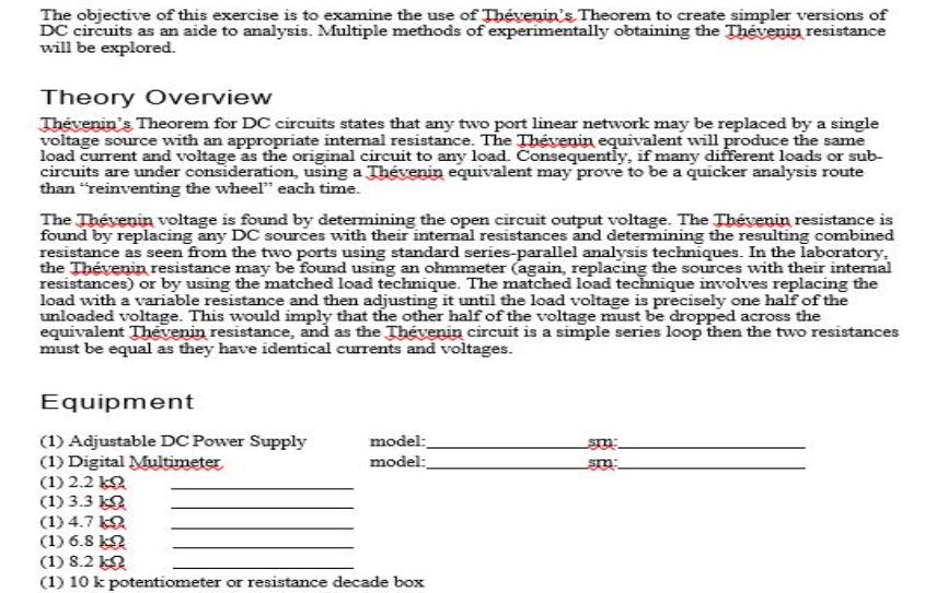
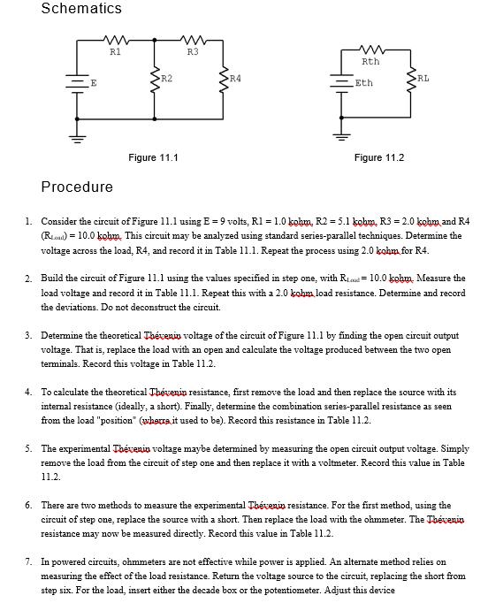
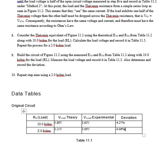
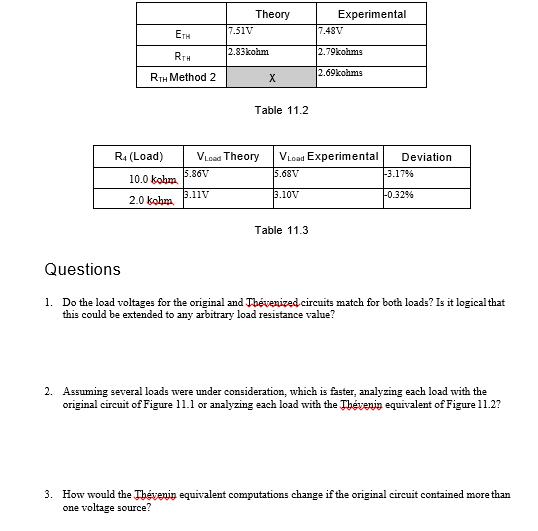
The objective of this exercise is to examine the use of Thévenin's Theorem to create simpler versions of DC circuits as an aide to analysis. Multiple methods of experimentally obtaining the Thévenin resistance will be explored. Theory Overview Thevenin's Theorem for DC circuits states that any two port linear network may be replaced by a single voltage source with an appropriate internal resistance. The Thévenin equivalent will produce the same load current and voltage as the original circuit to any load. Consequently, if many different loads or sub- circuits are under consideration, using a Thévenin equivalent may prove to be a quicker analysis route than "reinventing the wheel" each time. The Thévenin voltage is found by determining the open circuit output voltage. The Thévenin resistance is found by replacing any DC sources with their internal resistances and determining the resulting combined resistance as seen from the two ports using standard series-parallel analysis techniques. In the laboratory, the Thévenin resistance may be found using an ohmmeter (again, replacing the sources with their internal resistances) or by using the matched load technique. The matched load technique involves replacing the load with a variable resistance and then adjusting it until the load voltage is precisely one half of the unloaded voltage. This would imply that the other half of the voltage must be dropped across the equivalent Thévenin resistance, and as the Thévenin circuit is a simple series loop then the two resistances must be equal as they have identical currents and voltages. Equipment (1) Adjustable DC Power Supply (1) Digital Multimeter (1) 2.2 k (1) 3.3 k (1) 4.7 k (1) 6.8 k (1) 8.2 k (1) 10 k potentiometer or resistance decade box model: model: m sm: Schematics E www R1 Procedure R2 Figure 11.1 R3 R4 m Rth Eth Figure 11.2 RL 1. Consider the circuit of Figure 11.1 using E = 9 volts, R1 = 1.0 kohm, R2 = 5.1 kohm, R3 = 2.0 kohm, and R4 (Red) = 10.0 kohm. This circuit may be analyzed using standard series-parallel techniques. Determine the voltage across the load, R4, and record it in Table 11.1. Repeat the process using 2.0 kohm for R4. 2. Build the circuit of Figure 11.1 using the values specified in step one, with R 10.0 kohm, Measure the load voltage and record it in Table 11.1. Repeat this with a 2.0 kohm load resistance. Determine and record the deviations. Do not deconstruct the circuit. 3. Determine the theoretical Thévenin voltage of the circuit of Figure 11.1 by finding the open circuit output voltage. That is, replace the load with an open and calculate the voltage produced between the two open terminals. Record this voltage in Table 11.2. 4. To calculate the theoretical Thévenin resistance, first remove the load and then replace the source with its internal resistance (ideally, a short). Finally, determine the combination series-parallel resistance as seen from the load "position" (where it used to be). Record this resistance in Table 11.2. 5. The experimental Thévenia voltage maybe determined by measuring the open circuit output voltage. Simply remove the load from the circuit of step one and then replace it with a voltmeter. Record this value in Table 11.2. 6. There are two methods to measure the experimental Thévenin resistance. For the first method, using the circuit of step one, replace the source with a short. Then replace the load with the ohmmeter. The Thévenin resistance may now be measured directly. Record this value in Table 11.2. 7. In powered circuits, ohmmeters are not effective while power is applied. An alternate method relies on measuring the effect of the load resistance. Return the voltage source to the circuit, replacing the short from step six. For the load, insert either the decade box or the potentiometer. Adjust this device until the load voltage is half of the open circuit voltage measured in step five and record in Table 11.2 under "Method 2". At this point, the load and the Thévenin resistance form a simple series loop as seen in Figure 11.2. This means that they "see" the same current. If the load exhibits one half of the Thévenin voltage then the other half must be dropped across the Thévenin resistance, that is VRL= VRTH. Consequently, the resistances have the same voltage and current, and therefore must have the same resistance according to Ohm's Law. 8. Consider the Thévenin equivalent of Figure 11.2 using the theoretical ETH and RH from Table 11.2 along with 10.0 kohm for the load (RL). Calculate the load voltage and record it in Table 11.3. Repeat the process for a 2.0 kohm, load. 9. Build the circuit of Figure 11.2 using the measured ETH and RH from Table 11.2 along with 10.0 kohm for the load (RL). Measure the load voltage and record it in Table 11.3. Also determine and record the deviation. 10. Repeat step nine using a 2.0 kohm load. Data Tables Original Circuit R₁ (Load) 10.0 kohm 2.0 kohm VLoad Theory 5.86V 3.11V VLoad Experimental Deviation 5.62V 3.08V Table 11.1 -4.27% -0.96% ETH RTH RTH Method 2 R₁ (Load) 10.0 kohm 2.0 kohm 7.51V 5.86V 3.11V Theory 2.83kohm VLoad Theory X Table 11.2 3.10V Experimental Table 11.3 7.48V VLoad Experimental 5.68V 2.79kohms 2.69kohms Deviation -3.17% -0.32% Questions 1. Do the load voltages for the original and Thévenized circuits match for both loads? Is it logical that this could be extended to any arbitrary load resistance value? 2. Assuming several loads were under consideration, which is faster, analyzing each load with the original circuit of Figure 11.1 or analyzing each load with the Thévenin equivalent of Figure 11.27 3. How would the Thévenin equivalent computations change if the original circuit contained more than one voltage source? The objective of this exercise is to examine the use of Thévenin's Theorem to create simpler versions of DC circuits as an aide to analysis. Multiple methods of experimentally obtaining the Thévenin resistance will be explored. Theory Overview Thevenin's Theorem for DC circuits states that any two port linear network may be replaced by a single voltage source with an appropriate internal resistance. The Thévenin equivalent will produce the same load current and voltage as the original circuit to any load. Consequently, if many different loads or sub- circuits are under consideration, using a Thévenin equivalent may prove to be a quicker analysis route than "reinventing the wheel" each time. The Thévenin voltage is found by determining the open circuit output voltage. The Thévenin resistance is found by replacing any DC sources with their internal resistances and determining the resulting combined resistance as seen from the two ports using standard series-parallel analysis techniques. In the laboratory, the Thévenin resistance may be found using an ohmmeter (again, replacing the sources with their internal resistances) or by using the matched load technique. The matched load technique involves replacing the load with a variable resistance and then adjusting it until the load voltage is precisely one half of the unloaded voltage. This would imply that the other half of the voltage must be dropped across the equivalent Thévenin resistance, and as the Thévenin circuit is a simple series loop then the two resistances must be equal as they have identical currents and voltages. Equipment (1) Adjustable DC Power Supply (1) Digital Multimeter (1) 2.2 k (1) 3.3 k (1) 4.7 k (1) 6.8 k (1) 8.2 k (1) 10 k potentiometer or resistance decade box model: model: m sm: Schematics E www R1 Procedure R2 Figure 11.1 R3 R4 m Rth Eth Figure 11.2 RL 1. Consider the circuit of Figure 11.1 using E = 9 volts, R1 = 1.0 kohm, R2 = 5.1 kohm, R3 = 2.0 kohm, and R4 (Red) = 10.0 kohm. This circuit may be analyzed using standard series-parallel techniques. Determine the voltage across the load, R4, and record it in Table 11.1. Repeat the process using 2.0 kohm for R4. 2. Build the circuit of Figure 11.1 using the values specified in step one, with R 10.0 kohm, Measure the load voltage and record it in Table 11.1. Repeat this with a 2.0 kohm load resistance. Determine and record the deviations. Do not deconstruct the circuit. 3. Determine the theoretical Thévenin voltage of the circuit of Figure 11.1 by finding the open circuit output voltage. That is, replace the load with an open and calculate the voltage produced between the two open terminals. Record this voltage in Table 11.2. 4. To calculate the theoretical Thévenin resistance, first remove the load and then replace the source with its internal resistance (ideally, a short). Finally, determine the combination series-parallel resistance as seen from the load "position" (where it used to be). Record this resistance in Table 11.2. 5. The experimental Thévenia voltage maybe determined by measuring the open circuit output voltage. Simply remove the load from the circuit of step one and then replace it with a voltmeter. Record this value in Table 11.2. 6. There are two methods to measure the experimental Thévenin resistance. For the first method, using the circuit of step one, replace the source with a short. Then replace the load with the ohmmeter. The Thévenin resistance may now be measured directly. Record this value in Table 11.2. 7. In powered circuits, ohmmeters are not effective while power is applied. An alternate method relies on measuring the effect of the load resistance. Return the voltage source to the circuit, replacing the short from step six. For the load, insert either the decade box or the potentiometer. Adjust this device until the load voltage is half of the open circuit voltage measured in step five and record in Table 11.2 under "Method 2". At this point, the load and the Thévenin resistance form a simple series loop as seen in Figure 11.2. This means that they "see" the same current. If the load exhibits one half of the Thévenin voltage then the other half must be dropped across the Thévenin resistance, that is VRL= VRTH. Consequently, the resistances have the same voltage and current, and therefore must have the same resistance according to Ohm's Law. 8. Consider the Thévenin equivalent of Figure 11.2 using the theoretical ETH and RH from Table 11.2 along with 10.0 kohm for the load (RL). Calculate the load voltage and record it in Table 11.3. Repeat the process for a 2.0 kohm, load. 9. Build the circuit of Figure 11.2 using the measured ETH and RH from Table 11.2 along with 10.0 kohm for the load (RL). Measure the load voltage and record it in Table 11.3. Also determine and record the deviation. 10. Repeat step nine using a 2.0 kohm load. Data Tables Original Circuit R₁ (Load) 10.0 kohm 2.0 kohm VLoad Theory 5.86V 3.11V VLoad Experimental Deviation 5.62V 3.08V Table 11.1 -4.27% -0.96% ETH RTH RTH Method 2 R₁ (Load) 10.0 kohm 2.0 kohm 7.51V 5.86V 3.11V Theory 2.83kohm VLoad Theory X Table 11.2 3.10V Experimental Table 11.3 7.48V VLoad Experimental 5.68V 2.79kohms 2.69kohms Deviation -3.17% -0.32% Questions 1. Do the load voltages for the original and Thévenized circuits match for both loads? Is it logical that this could be extended to any arbitrary load resistance value? 2. Assuming several loads were under consideration, which is faster, analyzing each load with the original circuit of Figure 11.1 or analyzing each load with the Thévenin equivalent of Figure 11.27 3. How would the Thévenin equivalent computations change if the original circuit contained more than one voltage source?
Expert Answer:
Answer rating: 100% (QA)
1 Answer The load voltages for original and Thevenized circuit are very much same There is a maximum ... View the full answer

Related Book For 

Government and Not for Profit Accounting Concepts and Practices
ISBN: 978-1118155974
6th edition
Authors: Michael H. Granof, Saleha B. Khumawala
Posted Date:
Students also viewed these mathematics questions
-
The objective of this exercise is to familiarize you with the audited nancial statements and IRS Form 990 of a Nonprot Entity, the American Cancer Society (www.cancer.org). Obtain the audited nancial...
-
The purpose of this exercise is to present a scenario that requires you to act in the role of business intelligence (BI) consultant for your university (or college) and produce a report to guide...
-
The purpose of this exercise is to provide practice using LINGO or Excel Solver. Find the values of X and Y that minimize the function Min X2 - 4X + Y2 + 8Y + 20 Do not assume non-negativity of the X...
-
Molly earns a gross yearly salary of $132,676. She has no dependent children and made the following tax deductible purchases: Charitable contributions: $5,401 Student loan interest: $1,429 When she...
-
Compass Inc. purchased 1,250 bags of insulation from Glassco Inc. The bags of insulation cost $5.50 each. Compass paid Turner Trucking $320 to have the bags of insulation shipped to its warehouse....
-
An advantage in using statistical sampling over non-statistical sampling methods in tests of control is that statistical methods: (a) eliminate the need to use judgement in determining appropriate...
-
On July 1, Chi Kong creates a petty cash fund with a balance of $300. During July, Elise Sautter, the fund custodian, signs the following petty cash tickets: Petty Cash Ticket Number 101 102 103...
-
Shorts Company has three process departments: Mixing, Encapsulating, and Bottling. At the beginning of the year, there were no work-in-process or finished goods inventories. The following data are...
-
Problem 6. An equity securities market model follows a multi-period binomial model. At each node of the binomial tree the current stock price S will branch to us in the upstate and dS in the...
-
Mahalo Boat Adventure Inc. has a July 31 year-end. It showed the following partial amortization schedules regarding two bond issues: Required Answer the following for each bond issue: a. Were the...
-
Consider the following relation with sample data. DEPARTMENT OF TRANSPORTATION (DOT) PROJECT TABLE Projectib ProjectName CountylD CountyName ProjectManagerID ProjectManagerName...
-
Arndt, Incorporated reported the following for 2024 and 2025 ($ in millions): Revenues 2024 $948 2025 $ 1,040 Expenses Pretax accounting income (income statement) 804 $144 Taxable income (tax return)...
-
Global Trade Ltd (Global Trade), a key player in the international shipping industry, maintains a worldwide presence. The company is registered in Australia, with its headquarters situated in Sydney....
-
Contracts and Intentional Torts No unread replies.No replies. Module objectives: 1. Display in your discussion answer an understanding of the elements of a contract.2. Understand the type of...
-
Write the expression in the form a + bi. -6--54 3 -6--54 3
-
Write Matlab program to sort the following numbers into two groups: the first group contains numbers greater than 100 and the second group contains numbers less than or equal 100. Evaluate and print...
-
1. Find the area of each polygon 5" 7" | 5" 9" 2. Identify the length and width for a rectangle that has a perimeter of 20 cm and an area that is 21 cm. 3. Draw a square whose perimeter is equal to...
-
All of the following assets can be depreciated, except: (a) A bulldozer (b) A copper mine (c) A surgical robot (d) A conveyor belt
-
Why may a governments reported pension expenditure differ from its annual pension cost?
-
In the year a road maintenance district was established, it engaged in the transactions that follow involving capital assets (all dollar amounts in thousands). The district maintains only a single...
-
The Alpine school district engaged in the following transactions in its scal year ending August 31, 2015. By law, the district is required to establish a capital projects fund to account for school...
-
a. Nonlinearity in mass b. Nonlinearity in damping c. Linear equation d. Nonlinearity in spring \(\ddot{x}+f \frac{\dot{x}}{|\dot{x}|}+\omega_{n}^{2} x=0\)
-
The equation of motion of a nonlinear system is given by \[\ddot{x}+c \dot{x}+k_{1} x+k_{2} x^{2}=a \cos 2 \omega t\] Investigate the subharmonic solution of order 2 for this system.
-
Prove that, for the system considered in Section 13.5.1, the minimum value of \(\omega^{2}\) for which the amplitude of subharmonic oscillations \(A\) will have a real value is given by...

Study smarter with the SolutionInn App