

Using 95% reliability, repeat problem 4.4, but now use the AGMA method to determine both the...
Fantastic news! We've Found the answer you've been seeking!
Question:
Transcribed Image Text:
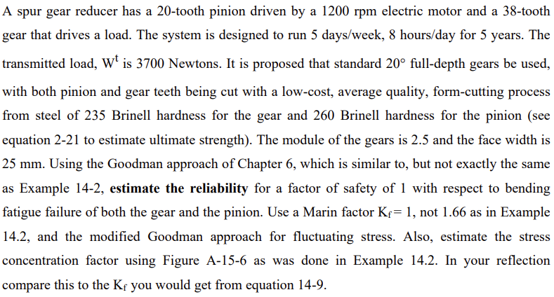
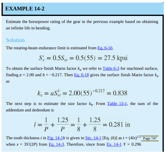
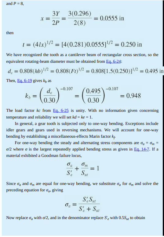
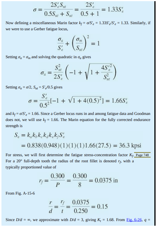
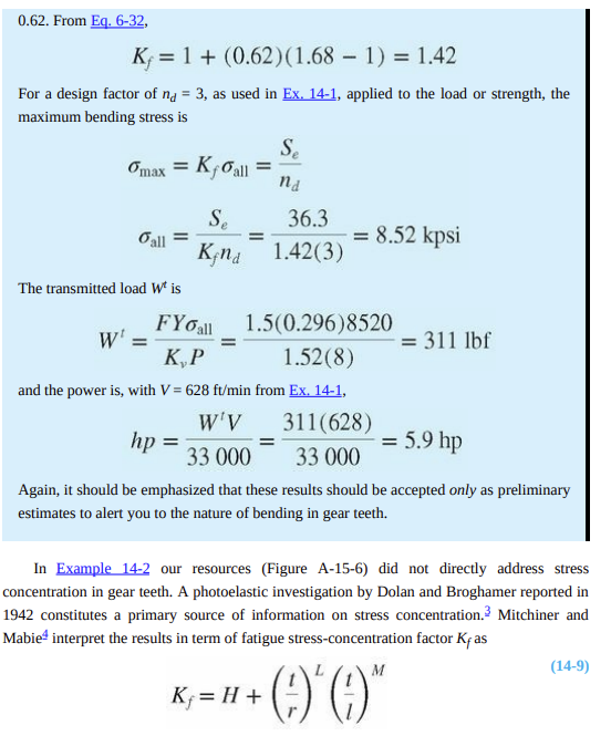
Using 95% reliability, repeat problem 4.4, but now use the AGMA method to determine both the bending and contact (surface) fatigue factors of safety for the pinion and the gear. State all assumptions and be sure to reflect on how answers to 4.4 and 4.5 compare and which you think is more conservative and which is more accurate. A spur gear reducer has a 20-tooth pinion driven by a 1200 rpm electric motor and a 38-tooth gear that drives a load. The system is designed to run 5 days/week, 8 hours/day for 5 years. The transmitted load, Wt is 3700 Newtons. It is proposed that standard 20 full-depth gears be used, with both pinion and gear teeth being cut with a low-cost, average quality, form-cutting process from steel of 235 Brinell hardness for the gear and 260 Brinell hardness for the pinion (see equation 2-21 to estimate ultimate strength). The module of the gears is 2.5 and the face width is 25 mm. Using the Goodman approach of Chapter 6, which is similar to, but not exactly the same as Example 14-2, estimate the reliability for a factor of safety of 1 with respect to bending fatigue failure of both the gear and the pinion. Use a Marin factor Kf= 1, not 1.66 as in Example 14.2, and the modified Goodman approach for fluctuating stress. Also, estimate the stress concentration factor using Figure A-15-6 as was done in Example 14.2. In your reflection compare this to the Kf you would get from equation 14-9. EXAMPLE 14-2 Estimate the horsepower rating of the gear in the previous example based on obtaining an infinite life in bending. Solution The rotating-beam endurance limit is estimated from Eq. 6-10, S'e = 0.5Sut = 0.5(55) = 27.5 kpsi To obtain the surface finish Marin factor ka we refer to Table 6-3 for machined surface, finding a = 2.00 and b = -0.217. Then Eq. 6-18 gives the surface finish Marin factor ka as ka = as = 2.00(55)- = 0.838 The next step is to estimate the size factor kb. From Table 13-1, the sum of the addendum and dedendum is 1 1.25 1 1.25 = + 8 P 8 The tooth thickness t in Fig. 14-1b is given in Sec. 14-1 [Eq. (b)] as t = when x = 3Y/(2P) from Eq. 14-3. Therefore, since from Ex. 14-1 Y = 0.296 + = 0.281 in = (41x)1/2 Page 747 and P = 8, then kt X = = 3Y 3(0.296) 2(8) 2P 1 = (41x)/ = [4(0.281)0.05551/ = 0.250 in We have recognized the tooth as a cantilever beam of rectangular cross section, so the equivalent rotating-beam diameter must be obtained from Eq. 6-24: de = 0.808(hb)/2 = 0.808(Ft)/2 = 0.808[1.5(0.250)]/2 = 0.495 in Then, Eq. 6-19 gives k, as = de 0.30 -0.107 = 0.0555 in = 0.495 0.30 -0.107 6m oa + = 1 S' ut = 0.948 The load factor kc from Eq. 6-25 is unity. With no information given concerning temperature and reliability we will set kd = ke = 1. In general, a gear tooth is subjected only to one-way bending. Exceptions include idler gears and gears used in reversing mechanisms. We will account for one-way bending by establishing a miscellaneous-effects Marin factor kf. For one-way bending the steady and alternating stress components are og = m = o/2 where o is the largest repeatedly applied bending stress as given in Eq. 14-7. If a material exhibited a Goodman failure locus, Since og and om are equal for one-way bending, we substitute o for om and solve the preceding equation for %, giving S'e Sut S'e + Sut Now replaced with o/2, and in the denominator replace S'e with 0.55ut to obtain 2S' Sut 0.5Sut + Sut Now defining a miscellaneous Marin factor kf = a/S'e = 1.33S'e/S'e = 1.33. Similarly, if we were to use a Gerber fatigue locus, 6 = 0 = oa S' oa = 5m Sut Setting %a = om and solving the quadratic in o gives From Fig. A-15-6 + Se = kakok kakekfS d = 6, 2S' 0.5 + 1 2 ut -S (-1 + +45 2) 1 2S ut Setting % = 0/2, Sut = S'e/0.5 gives S' 0.5 and kf=o/S'e = 1.66. Since a Gerber locus runs in and among fatigue data and Goodman does not, we will use kf = 1.66. The Marin equation for the fully corrected endurance strength is = = = 1 [-1 + 1 +4(0.5)] = 1.66S = 1.33S = 0.838 (0.948)(1)(1)(1)1.66(27.5) = 36.3 kpsi For stress, we will first determine the fatigue stress-concentration factor Kf. Page 748 For a 20 full-depth tooth the radius of the root fillet is denoted rf, with a typically proportioned value of 0.300 0.300 P 8 = 0.0375 in r 0.0375 d 0.250 Since D/d = , we approximate with D/d = 3, giving K, = 1.68. From Fig. 6-26, q = = 0.15 0.62. From Eq. 6-32, K 1+ (0.62) (1.68 - 1) = 1.42 For a design factor of na = 3, as used in Ex. 14-1, applied to the load or strength, the maximum bending stress is omax = Kfall Se Kfnd Gall = The transmitted load Wt is = W' = Se nd 36.3 1.42(3) FYo all K,P and the power is, with V=628 ft/min from Ex. 14-1, W'V 311(628) hp = 5.9 hp 33 000 33 000 Again, it should be emphasized that these results should be accepted only as preliminary estimates to alert you to the nature of bending in gear teeth. = = 8.52 kpsi 1.5(0.296)8520 1.52(8) Kf = H + In Example 14-2 our resources (Figure A-15-6) did not directly address stress concentration in gear teeth. A photoelastic investigation by Dolan and Broghamer reported in 1942 constitutes a primary source of information on stress concentration. Mitchiner and Mabie interpret the results in term of fatigue stress-concentration factor Kas M + )*(* = 311 lbf (14-9) Using 95% reliability, repeat problem 4.4, but now use the AGMA method to determine both the bending and contact (surface) fatigue factors of safety for the pinion and the gear. State all assumptions and be sure to reflect on how answers to 4.4 and 4.5 compare and which you think is more conservative and which is more accurate. A spur gear reducer has a 20-tooth pinion driven by a 1200 rpm electric motor and a 38-tooth gear that drives a load. The system is designed to run 5 days/week, 8 hours/day for 5 years. The transmitted load, Wt is 3700 Newtons. It is proposed that standard 20 full-depth gears be used, with both pinion and gear teeth being cut with a low-cost, average quality, form-cutting process from steel of 235 Brinell hardness for the gear and 260 Brinell hardness for the pinion (see equation 2-21 to estimate ultimate strength). The module of the gears is 2.5 and the face width is 25 mm. Using the Goodman approach of Chapter 6, which is similar to, but not exactly the same as Example 14-2, estimate the reliability for a factor of safety of 1 with respect to bending fatigue failure of both the gear and the pinion. Use a Marin factor Kf= 1, not 1.66 as in Example 14.2, and the modified Goodman approach for fluctuating stress. Also, estimate the stress concentration factor using Figure A-15-6 as was done in Example 14.2. In your reflection compare this to the Kf you would get from equation 14-9. EXAMPLE 14-2 Estimate the horsepower rating of the gear in the previous example based on obtaining an infinite life in bending. Solution The rotating-beam endurance limit is estimated from Eq. 6-10, S'e = 0.5Sut = 0.5(55) = 27.5 kpsi To obtain the surface finish Marin factor ka we refer to Table 6-3 for machined surface, finding a = 2.00 and b = -0.217. Then Eq. 6-18 gives the surface finish Marin factor ka as ka = as = 2.00(55)- = 0.838 The next step is to estimate the size factor kb. From Table 13-1, the sum of the addendum and dedendum is 1 1.25 1 1.25 = + 8 P 8 The tooth thickness t in Fig. 14-1b is given in Sec. 14-1 [Eq. (b)] as t = when x = 3Y/(2P) from Eq. 14-3. Therefore, since from Ex. 14-1 Y = 0.296 + = 0.281 in = (41x)1/2 Page 747 and P = 8, then kt X = = 3Y 3(0.296) 2(8) 2P 1 = (41x)/ = [4(0.281)0.05551/ = 0.250 in We have recognized the tooth as a cantilever beam of rectangular cross section, so the equivalent rotating-beam diameter must be obtained from Eq. 6-24: de = 0.808(hb)/2 = 0.808(Ft)/2 = 0.808[1.5(0.250)]/2 = 0.495 in Then, Eq. 6-19 gives k, as = de 0.30 -0.107 = 0.0555 in = 0.495 0.30 -0.107 6m oa + = 1 S' ut = 0.948 The load factor kc from Eq. 6-25 is unity. With no information given concerning temperature and reliability we will set kd = ke = 1. In general, a gear tooth is subjected only to one-way bending. Exceptions include idler gears and gears used in reversing mechanisms. We will account for one-way bending by establishing a miscellaneous-effects Marin factor kf. For one-way bending the steady and alternating stress components are og = m = o/2 where o is the largest repeatedly applied bending stress as given in Eq. 14-7. If a material exhibited a Goodman failure locus, Since og and om are equal for one-way bending, we substitute o for om and solve the preceding equation for %, giving S'e Sut S'e + Sut Now replaced with o/2, and in the denominator replace S'e with 0.55ut to obtain 2S' Sut 0.5Sut + Sut Now defining a miscellaneous Marin factor kf = a/S'e = 1.33S'e/S'e = 1.33. Similarly, if we were to use a Gerber fatigue locus, 6 = 0 = oa S' oa = 5m Sut Setting %a = om and solving the quadratic in o gives From Fig. A-15-6 + Se = kakok kakekfS d = 6, 2S' 0.5 + 1 2 ut -S (-1 + +45 2) 1 2S ut Setting % = 0/2, Sut = S'e/0.5 gives S' 0.5 and kf=o/S'e = 1.66. Since a Gerber locus runs in and among fatigue data and Goodman does not, we will use kf = 1.66. The Marin equation for the fully corrected endurance strength is = = = 1 [-1 + 1 +4(0.5)] = 1.66S = 1.33S = 0.838 (0.948)(1)(1)(1)1.66(27.5) = 36.3 kpsi For stress, we will first determine the fatigue stress-concentration factor Kf. Page 748 For a 20 full-depth tooth the radius of the root fillet is denoted rf, with a typically proportioned value of 0.300 0.300 P 8 = 0.0375 in r 0.0375 d 0.250 Since D/d = , we approximate with D/d = 3, giving K, = 1.68. From Fig. 6-26, q = = 0.15 0.62. From Eq. 6-32, K 1+ (0.62) (1.68 - 1) = 1.42 For a design factor of na = 3, as used in Ex. 14-1, applied to the load or strength, the maximum bending stress is omax = Kfall Se Kfnd Gall = The transmitted load Wt is = W' = Se nd 36.3 1.42(3) FYo all K,P and the power is, with V=628 ft/min from Ex. 14-1, W'V 311(628) hp = 5.9 hp 33 000 33 000 Again, it should be emphasized that these results should be accepted only as preliminary estimates to alert you to the nature of bending in gear teeth. = = 8.52 kpsi 1.5(0.296)8520 1.52(8) Kf = H + In Example 14-2 our resources (Figure A-15-6) did not directly address stress concentration in gear teeth. A photoelastic investigation by Dolan and Broghamer reported in 1942 constitutes a primary source of information on stress concentration. Mitchiner and Mabie interpret the results in term of fatigue stress-concentration factor Kas M + )*(* = 311 lbf (14-9)
Expert Answer:

Related Book For 
Shigleys Mechanical Engineering Design
ISBN: 978-1121345317
9th edition
Authors: Richard G. Budynas, J. Keith Nisbett
Posted Date:
Students also viewed these mechanical engineering questions
-
What are two major solutions that exist to optimize the query propagation process and to limit the amount of unnecessary EIGRP load on the links?
-
Analytics mindset Final Project 4 Gamification Part 1: Background You are the chief technology officer (CTO) of an international bank. A key component of your job is to manage risk within the bank...
-
The problem in our initial discussion of A-grade insurance markets was that adverse selection led to non-randomness in the insurance pool: Although almost everyone was willing to pay the insurance...
-
Why are process control systems necessary? Give TWO examples of their usefulness within the plant.
-
What are the three steps used to analyze a significant interaction?
-
The following selected transactions apply to Topeca Supply for November and December Year 1. November was the first month of operations. Sales tax is collected at the time of sale but is not paid to...
-
List five components of job satisfaction and briefly discuss their importance.
-
On the next page is the net income of Anita Ferreri Instrument Co., a private corporation, computed under the three inventory methods using a periodic system. Instructions (Ignore tax...
-
Logistics Solutions provides order fulfillment services for dot.com merchants. The company maintains warehouses that stock items carried by its dot.com clients. When a client receives an order from a...
-
A month has elapsed since Precision Computer Centre's year-end. Tony Freedman will use four specialized journals for recording business transactions in the month of September. To assist you in...
-
Petunia Company acquired an 80% interest in Shaman Company in 2016. In 2017 and 2018, Shaman reported net income of $400,000 and $480,000, respectively. During 2017, Shaman sold $80,000 of...
-
The U.S. Navy has built the Sea Shadow, which is a small waterplane twin-hull (SWATH) ship whose object is to achieve the same reduced radar profile as the STEALTH aircraft. This catamaran is \(160...
-
Why is it necessary to serve nonparty witnesses with a subpoena to appear at trial?
-
Jill Corp is subject to tax in only one state. During the year, it generated the following: Federal taxable income is $1,200,000. What is the corporations state taxable income? Depreciation for...
-
What does the phrase theory of the case mean? Why is it important to develop a theory of the case in advance of trial?
-
Identify the two ways that trial material may be organized. What are the advantages and disadvantages of each method?
-
A check valve will and allow, reverse flow in one direction, flow in the other direction. O allow, stop stop, decrease allow, increase
-
On October 1, 2014, the Dow Jones Industrial Average (DJIA) opened at 17,042 points. During that day it lost 237 points. On October 2 it lost 4 points. On October 3 it gained 209 points. Deter-mine...
-
The shaft shown in the figure is proposed as a preliminary design for the application defined in Prob. 373, p. 138. The effective centers of the gears for force transmission are shown. The dimensions...
-
Listed in the tables are six springs described in customary units and five springs described in SI units. Investigate these squared-and-ground-ended helical compression springs to see if they are...
-
The shaft shown in Prob. 719 is proposed for the application defined in Prob. 372, p. 138. Specify a square key for gear B, using a factor of safety of 1.1. In Prob. 719, The shaft shown in the...
-
A company acquires equipment on January 10, 2005, at a cost of $42,000. Straight-line depreciation is used with a five-year life and $7,000 salvage value. On June 27, 2006, the company sells this...
-
hsteban Co. owns a machine that costs $38,400 with accumulated depreciation of $20,400. Esteban exchanges the machine for a similar but newer model that has a market value of $48,000. Record the...
-
Eastman Company reports the following ($ millions): net sales of $13,557 for 2005 and $12,670 for 2004; end-of-year total assets of $14,968 for 2005 and $18,810 for 2004. Compute its total asset...

Study smarter with the SolutionInn App